
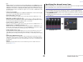
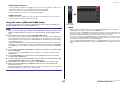
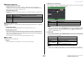
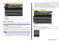
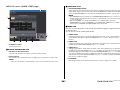
EN
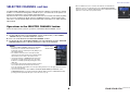
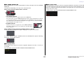
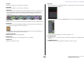
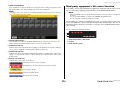
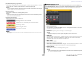
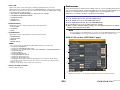
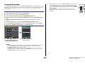
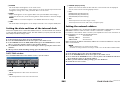
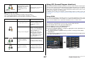
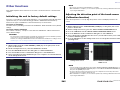
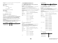
How to Use This Reference Manual
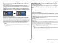
The CL5/CL3/CL1 Reference Manual (this document) allows you
to search for terms and take advantage of links in the text.
Searching for terms
To search for a term, use the search function of the software
you’re using to view this document.
If you’re using Adobe Reader, enter the term in the search box
and press the <Enter> key of your computer keyboard to search
for occurrences of that term.
Displaying the next/previous view
If you’re using Adobe Reader, you can jump to the previous/next
view in your viewing history. This is a convenient way to jump back
to the previous page after you’ve used a link to jump to a different
page.
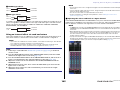
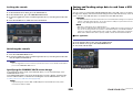
Using the Function Tree
A function tree for the CL series is provided on page 4 and
following. You can use this function tree to find the page that
explains an on-screen display or function.
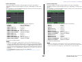
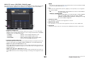
Reference Manual

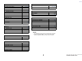
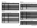
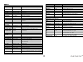
Contents
Reference Manual
2
Contents
How to Use This Reference Manual .......................................................................... 1
Function Tree ............................................................................ 4
SELECTED CHANNEL section ...................................................... 6
Operations in the SELECTED CHANNEL Section ....................................................... 6
Centralogic section ................................................................. 13
Operations in the Centralogic section .................................................................... 13
Input and output patching..................................................... 18
CL console internal patching and Dante audio network patching .......................... 18
Changing the input patching ................................................................................ 19
Changing the output patching .............................................................................. 20
Inserting an external device into a channel ............................................................ 23
Directly outputting an INPUT channel ................................................................... 26
Input channels ........................................................................ 28
Signal flow for input channels................................................................................ 28
Specifying the channel name/icon ......................................................................... 29
HA (head amp) settings ......................................................................................... 31
Sending the signal from an input channel to the STEREO/MONO bus ................... 37
Added pan function (Monaural input channels only) ............................................. 40
Sending a signal from an input channel to a MIX/MATRIX bus .............................. 42
Channel name display indication ........................................................................... 46
Correcting delay between channels (Input Delay).................................................. 47
Surround output for input channels....................................................................... 50
Channel library operations..................................................................................... 54
OUTPUT channels.................................................................... 55
Signal flow for output channels ............................................................................. 55
Specifying the channel name/icon ......................................................................... 56
Sending signals from MIX channels to the STEREO/MONO bus ............................. 57
Sending signals from MIX channels and STEREO/MONO channels to
MATRIX buses............................................................................................. 59
Correcting delay between channels (Output Delay)............................................... 62
Channel library operations..................................................................................... 63
EQ and Dynamics ..................................................................... 64
Using EQ ................................................................................................................ 64
Using dynamics ...................................................................................................... 67
Using the EQ/Dynamics libraries............................................................................. 70
Channel Job ............................................................................. 71
DCA group............................................................................................................. 71
DCA Roll-out function ............................................................................................ 74
Mute group............................................................................................................ 76
Using the Recall Safe function................................................................................. 79
Channel Link function ............................................................................................ 82
Copying, moving, or initializing a channel.............................................................. 87
About Mix Minus.................................................................................................... 91
Scene memory ......................................................................... 92
Storing and recalling scenes ................................................................................... 92
Editing scene memories.......................................................................................... 97
Using the Global Paste function.............................................................................. 99
Using the Focus Recall function ............................................................................ 102
Using the Fade function........................................................................................ 103
Outputting a control signal to an external device in tandem with scene recall
(GPI OUT) ................................................................................................. 105
Playing back an audio file that links to a scene recall............................................. 106
Using Preview mode............................................................................................. 108
Monitor and Cue functions ................................................... 109
Using the Monitor function .................................................................................. 110
Using the Cue function......................................................................................... 116
Talkback and Oscillator......................................................... 125
Using Talkback ..................................................................................................... 125
Using the Oscillator function ................................................................................ 127
Meters.................................................................................... 130
Operations in the METER screen ........................................................................... 130
Using an MBCL meter bridge (optional) on the CL3 or CL1 console ..................... 134
Graphic EQ, Parametric EQ, Effects, and PREMIUM RACK..... 135
About the virtual rack ........................................................................................... 135
Virtual rack operations.......................................................................................... 136
Graphic EQ operations ......................................................................................... 139
About AUTOMIXER............................................................................................... 146
Editing the internal effects .................................................................................... 148
Effects and tempo synchronization ....................................................................... 155

Contents
Reference Manual
3
Using the Premium Rack...................................................................................... 156
Using the graphic EQ, parametric EQ, effect, and Premium Rack libraries ............ 166
I/O devices and external head amps .................................... 167
Using an I/O device ............................................................................................. 167
Remotely controlling an R series unit ................................................................... 169
Third-party equipment’s HA control function....................................................... 173
Remotely controlling an amp............................................................................... 175
Remotely controlling WIRELESS unit..................................................................... 176
Using an external head amp ................................................................................ 178
MIDI....................................................................................... 183
MIDI functionality on the CL series console.......................................................... 183
Basic MIDI settings .............................................................................................. 183
Using program changes to recall scenes and library items.................................... 186
Using control changes to control parameters....................................................... 188
Using parameter changes to control parameters .................................................. 190
Recorder................................................................................ 191
About the USB memory recorder ......................................................................... 191
Assigning channels to the input/output of the recorder ....................................... 191
Recording audio to a USB flash drive.................................................................... 193
Playing back audio files from a USB flash drive ..................................................... 195
Editing the title list............................................................................................... 196
Recording or playing back using a computer DAW .............................................. 197
Using the CL console with Nuendo Live............................................................... 200
Setup ..................................................................................... 204
About the SETUP screen....................................................................................... 204
User settings ........................................................................................................ 206
Preferences .......................................................................................................... 213
USER DEFINED keys ............................................................................................. 215
Functions that can be assigned to USER DEFINED keys ........................................ 217
USER DEFINED knobs........................................................................................... 222
Functions that can be assigned to USER DEFINED knobs ...................................... 223
Assignable encoders ............................................................................................ 225
Functions that can be assigned to the assignable encoders .................................. 226
GAIN/PAN/ASSIGN knob (assignable encoder) functions ..................................... 227
Custom fader bank .............................................................................................. 227
Master fader ........................................................................................................ 228
Custom fader bank functions ............................................................................... 229
Console Lock ....................................................................................................... 229
Saving and loading setup data to and from a USB flash drive............................... 230
Formatting a USB flash drive................................................................................ 236
Word clock and slot settings................................................................................. 237
Using cascade connections ................................................................................... 239
Basic settings for MIX buses and MATRIX buses.................................................... 243
Switching the entire phantom power supply on/off.............................................. 244
Specifying the brightness of the touch screen, LEDs, channel name displays,
and lamps ................................................................................................. 244
Setting the date and time of the internal clock ..................................................... 245
Setting the network address ................................................................................. 245
Dante audio network settings ............................................................................... 246
Using GPI (General Purpose Interface) .................................................................. 257
Help function......................................................................... 263
Loading a Help/text file from a USB flash drive ..................................................... 263
Viewing Help........................................................................................................ 263
Using USER DEFINED keys to recall Help directly................................................... 264
Other functions ..................................................................... 265
Initializing the unit to factory default settings ....................................................... 265
Adjusting the detection point of the touch screen (Calibration function) .............. 265
Adjusting the faders (Calibration function) ........................................................... 266
Fine-tuning the input and output gain (Calibration function) ............................... 266
Adjusting the channel color (Calibration function)................................................ 268
Adjusting the brightness of the channel name display .......................................... 268
Adjusting the contrast of the channel name display.............................................. 269
Initializing the console settings and Dante audio network settings........................ 269
Update procedure for NAME SUB CPU firmware................................................... 270
Update function to Dante firmware ...................................................................... 270
Warning/Error Messages ...................................................... 271
Index...................................................................................... 274

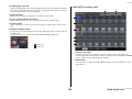
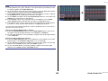
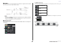
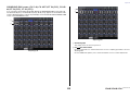
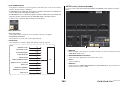
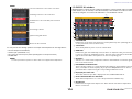
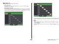
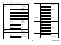
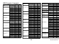
Function Tree
Reference Manual
4
Function Tree
Page numbers in parentheses ( ) are the page numbers of the
Owner’s Manual(booklet).
Main
SELECTED CHANNEL 6
OVERVIEW 14
FUNCTION ACCESS AREA (18)
CHANNEL PARAMETER
PATCH/NAME 20, 30, 56
GAIN/PATCH 32
1ch 32
8ch 33
CH1-48 35
CH49-72/ST IN 35
OUTPUT
Indication only
INPUT DELAY 47
8ch 47
CH1-48 48
CH49-72/ST IN 48
DELAY SCALE 47
INSERT/DIRECT OUT 24
1ch 24, 26
8ch 25, 27
HPF/EQ 64
1ch 64
8ch 66
CH1-48 66
CH49-72/ST IN 66
OUTPUT 66
DYNAMICS 67
1ch 67
KEY IN SOURCE SELECT 68
8ch 69
CH1-48 70
CH49-72/ST IN 70
OUTPUT 70
CHANNEL PARAMETER
MIX SEND/MATRIX SEND 44
TO STEREO/MONO 57
8ch 57
CH1-48 58
CH49-72/ST IN 58
OUTPUT 58
SURROUND 50
LIBRARY
CHANNEL LIBRARY 54
EQ LIBRARY 70
DYNAMICS LIBRARY 70
GEQ/PEQ LIBRARY 166
EFFECT LIBRARY 166
Portico5033/Portico5043/U76/Opt-2A/
EQ-1A/DynamicEQ/Buss Comp 369/MBC4
LIBRARY
166
DANTE INPUT PATCH LIBRARY 168
RACK
VIRTUAL RACK 136
RACK MOUNTER 139
GEQ EDIT 140
RACK LINK 140
EFFECT RACK 150
EFFECT EDIT 150
EFFECT TYPE 150
PREMIUM RACK 156
PREMIUM RACK MOUNTER 156
PREMIUM RACK EDIT 157
AUTOMIXER 146
PARAMETRIC EQ 143
I/O DEVICE
DANTE PATCH 167
DANTE INPUT PATCH 168
OUTPUT PATCH 169
I/O 169
AMP 175
WIRELESS 176
EXTERNAL HA 180
EXTERNAL HA RACK 180
EXTERNAL HA EDIT 180
EXTERNAL HA PORT SELECT 181
MONITOR
MONITOR 110
CUE 120
MONITOR 112
OSCILLATOR 128
TALKBACK 126
METER
INPUT METER 130
OUTPUT METER 130
RTA METER 132
SETUP
USER SETUP 204
PREFERENCE 213
USER DEFINED KEYS SETUP 215
USER DEFINED KEY SETUP (List) 215
USER DEFINED KNOBS SETUP 222
USER DEFINED KNOB SETUP (List) 222
ASSIGNABLE ENCODER SETUP 225
CUSTOM FADER BANK/MASTER FADER 228
FADER ASSIGN SELECT 227
USER LEVEL/CREATE USER KEY 207
CREATE KEY 208
SAVE KEY 211
LOGIN 209
SAVE/LOAD 230
I/O DEVICE

Function Tree
Reference Manual
5
NOTE
• The explanations in this reference manual will use the CL5.
• In the case of the CL3/CL1, some screens will not show
channels and faders that do not exist on those models.
WORD CLOCK/SLOT SETUP 237
CASCADE IN/OUT PATCH 240, 242
OUTPUT PORT 62
MIDI/GPI 183, 257
MIDI SETUP 184
PROGRAM CHANGE 186
CONTROL CHANGE 189
GPI 258
FADER START 261
BUS SETUP 243
SURROUND SETUP 205
CONSOLE LOCK 229
DATE/TIME 245
NETWORK 246
DANTE SETUP 247
SCENE
SCENE LIST 94
GLOBAL PASTE 100
Fade time 104
SONG SELECT 107
FOCUS RECALL 102
RECORDER
USB 191
NUENDO LIVE 200
CH JOB
CH LINK MODE 83
DCA GROUP ASSIGN 72
MUTE GROUP ASSIGN 72
RECALL SAFE MODE 80
CH COPY MODE 87
CH MOVE MODE 89
CH DEFAULT MODE 90
SETUP PATCH
PORT SELECT
25, 27, 113, 121,
168, 241
CH SELECT 22, 137, 192, 228
Others
CONFIRMATION 214
SOFT KEYBORD (21)
LOGIN 209
Startup Menu
MODE SELECT 265
INITIALIZE ALL MEMORIES 265
INITIALIZE CURRENT MEMORIES 265
TOUCH SCREEN CALIBRATION 265
INPUT PORT TRIM 267
OUTPUT PORT TRIM 267
SLOT OUTPUT TRIM 267
FADER CALIBRATION 266
LED COLOR CALIBRATION 268

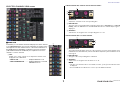
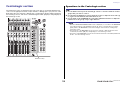
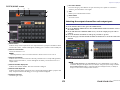
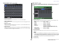
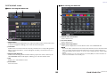
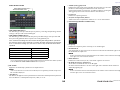
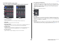
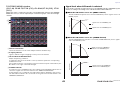
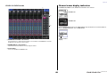
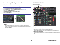
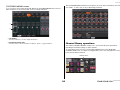
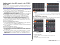
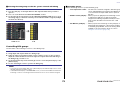
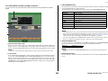
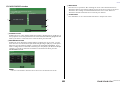
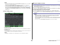
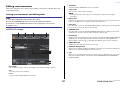
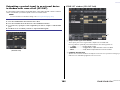
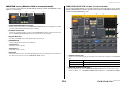
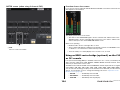
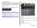
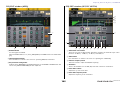
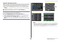
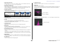
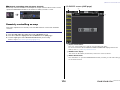
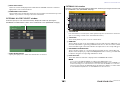
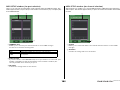
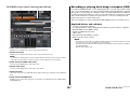
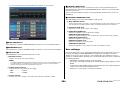
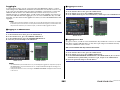
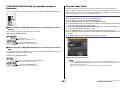
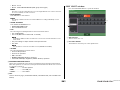
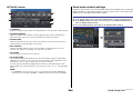
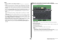
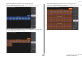
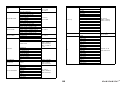
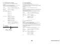
SELECTED CHANNEL section
Reference Manual
6
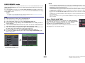
SELECTED CHANNEL section
The SELECTED CHANNEL section located at the left of the display corresponds to a channel
module of a conventional analog mixer, and allows you to use the knobs on the panel to set
all the major parameters of the currently-selected channel.
Operations in this section will affect the channel that was most recently selected by its [SEL]
key. If you have assigned an ST IN channel or STEREO channel to a single channel strip,
either the L or the R channel will be selected, and the major parameters for L and R channels
will be linked.
Operations in the SELECTED CHANNEL Section
Follow the steps below to perform operations in the SELECTED CHANNEL section.
NOTE
• To select a MIX or MATRIX channel, use the Bank
Select keys to recall the desired channel to the
Centralogic section, and then press the [SEL] key for
the desired channel.
• The number and name of the currently-selected
channel is shown in the channel select field located in
the Function Access Area of the touch screen.
• If an ST IN channel or STEREO channel has been
assigned to a single channel strip, you can switch
between L and R by repeatedly pressing the same
[SEL] key.
• You can also switch channels by pressing the channel
select field located in the Function Access Area.
Press the left side of the field to select the preceding channel. Press the right side of the field to
select the next channel.
• If you have turned on the option “POPUP APPEARS WHEN KNOB(S) PRESSED” on the
PREFERENCE tab (accessed by pressing the SETUP button, then the USER SETUP button),
pressing a knob repeatedly will open or close the screen (1 ch).
• Even if a different screen is selected, the channel selected with the
[SEL] key can be set using the knobs of the SELECTED CHANNEL
section. In this case, a window indicating the value of that parameter will
appear on screen when you operate a knob.
STEP
1. Use the [SEL] key in the top panel INPUT section, ST IN section, or the STEREO/
MONO section, to select the channel to control.
2. Press one of the knobs in the SELECTED CHANNEL section.
3. Use the knobs of the SELECTED CHANNEL section and the buttons in the SELECTED
CHANNEL VIEW screen to edit the parameters of the selected channel.
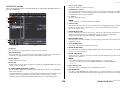
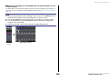
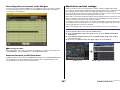
Channel number
Channel name

SELECTED CHANNEL section
Reference Manual
7
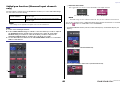
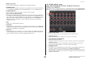
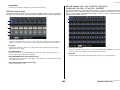
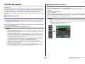
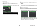
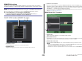
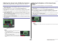
SELECTED CHANNEL VIEW screen
SEND field
In this field, you can view the send level and pre/post from the channel
to each MIX/MATRIX bus. You can also switch the on/off status of the
send signals. The view and the function of the knobs and buttons in
the SEND field vary depending on whether a pair of bus channels
(odd-numbered and even-numbered) are comprised of two mono
channels or a stereo channel.
1 Tabs
Enable you to select a group of 16 output bus channels to be
displayed in the SEND field.
• MIX1-16 tab............................ displays MIX buses 1-16.
• MIX17-24/MATRIX tab ........... displays MIX buses 17-24 and
MATRIX buses 1-8.
If the destination bus channels are two mono channels:
1 SEND knob
Adjusts the send level to the corresponding bus.
2 PRE indicator
The type of the corresponding bus is indicated. If the type is VARI [PRE EQ] or VARI [PRE
FADER], and if the PRE button on the MIX SEND 8ch screen is turned ON, the type is
displayed.
3 ON button
Switches the send signal to the corresponding bus on or off.
If the destination bus is a stereo channel:
1 SEND/PAN knob
The right-hand knob adjusts the level of the signal sent to a pair of bus channels (even-
numbered and odd-numbered). The left-hand knob adjusts the pan and balance of the
same signal.
2 PRE indicator
The type of the corresponding bus is indicated.
3 ON button
Switches the send signal to the two buses on or off.
NOTE
• If the type of the destination bus is set to FIXED, controllers 2 and 3 mentioned above will not
be displayed.
• Press the SEND knob or PAN knob on screen to open the SEND 8ch window.
1
1
2
3
1
2
3

SELECTED CHANNEL section
Reference Manual
8
When using CUE B
Indicates that channels 7 and 8 on the MATRIX
bus are combined with CUE B.
NOTE
For details about how to use CUE B, see the
CUE screen (When configuring CUE B).
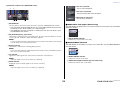
GAIN/PATCH field
This field enables you to make HA (head amp) analog or digital gain settings. You can also
view the operational status of the head amp.
1 GAIN knob
Sets the analog gain/digital gain of the head amp.
Press the knob to open the GAIN/PATCH 1ch window.
2 GC indicator
Indicates the fixed gain value output to the audio
network if the Gain Compensation function is turned
on.
3 OVER indicator
Warns you when the signal is clipping.
4 Ø (Phase) indicator
Indicates the status of the phase setting.
5 +48V indicator
Indicates the phantom power (+48V) on or off status for the head amp.
6 HPF ON indicator
Indicates the HPF on/off status of the external head amp.
7 AG-DG LINK indicator
Indicates a link between the analog gain and digital gain of the head amp.
8 Digital/Analog gain value
If analog gain is assigned to the GAIN knob, the digital gain value is shown here. If digital
gain is assigned to the GAIN knob, the analog gain value is shown here.
NOTE
• For an input channel that is patched to an input that has no head amp, 1, 2, 5, 6, and 7
will not be shown. For an output channel,
1 - 7 will not be shown.
• If a GAIN KNOB FUNCTION is set to DIGITAL GAIN in the USER SETUP PREFERENCE
screen, the digital gain knob will appear for
1, and 2, 5, 6, and 7 will not be displayed.
For details, refer to “HA (head amp) settings” (page 31).
If patched to a wireless mic (SELECTED CHANNEL VIEW screen)
1 RX.GAIN knob
Sets the gain for the receiver. Press the knob to open the
GAIN/PATCH 1ch window.
2 OL indicator
Lights if the audio signal level of the receiver reaches the
overload point.
3 RF (Radio Frequency) signal meter
Shows bars to indicate the level of the RF signal. An active
antenna indicator is shown on the right side. It indicates which antenna is enabled.
NOTE
For more information about the relationship between the number of bars and the actual strength
of the RF signal, refer to the manual from Shure.
4 Battery indicator
Shows bars to indicate the remaining battery power.
NOTE
For more information about the relationship between the number of bars and maximum operation
time, refer to the manual from Shure.
5 MUTE indicator
Indicates the mute status (on/off) of the audio signal for the receiver.
6 Frequency
Indicates the frequency that is currently set for the RF signal.
41
76
3
5
8
2
1
2
3
6
5
4

SELECTED CHANNEL section
Reference Manual
9
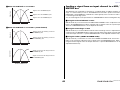
PAN/BALANCE field
This field enables you to switch the on/off status of the signal sent from the selected channel
to the STEREO/MONO bus, and adjust the pan and balance.
The view and the function of the controllers in this field vary depending on the type of the
selected channel.
When an input channel or MIX channel is selected:
1 TO STEREO PAN knob
Sets the pan position of a signal routed to the
STEREO bus.
Press the knob to open the STEREO/MONO 8ch
window. If the ST IN channel is selected, you can
specify whether to view the PAN knob or the
BALANCE knob in this window. For a MIX channel,
the PAN knob will appear if the signal is mono, and the BALANCE knob will appear if the
signal is stereo.
NOTE
• For mono input channels, the pan level is nominal at center and +3dB when panned either left or
right. These levels do not change even if channel link is used.
• For ST IN channels, if the PAN knob is selected, the pan level is nominal when panned either left
or right and -3dB at center. If the BALANCE knob is selected the balance level is nominal at
center and +3dB when panned either left or right. These levels do not change even if channel link
is used.
2 ST/MONO button
Switches the on/off status of a signal sent from the
channel to the STEREO/MONO bus.
If an INPUT/MIX channel is set to LCR mode, the
LCR button appears in location
2.The LCR button
is an overall on/off switch for the signals sent from
the channel to the STEREO/MONO bus.
When a MATRIX, STEREO, or MONO channel is selected:
1 BALANCE knob
If the signal on the selected channel is stereo, the
BALANCE knob will appear, enabling you to adjust
the volume balance for the left and right channels.
If the channel signal is monaural, the BALANCE
knob is not shown and cannot be used.
Press the knob to open the TO STEREO 8ch
window.
When using Surround mode (MIX1- MIX6)
3 DOWN MIX
This field enables you to view the downmix
coefficient and L/R button settings.
Press this field to open the TO STEREO/MONO
window.
INPUT DELAY field
This field enables you to view the delay settings.
1 ON indicator
Indicates the on/off status of the delay.
2 Delay time
The delay value is displayed by milliseconds (ms) and also by currently-selected scale. If
the scale uses units of ms, the value in the bottom row will not be displayed. Only the
ms value appears in the middle row.
Press this field to open the INPUT DELAY 8ch window.
HPF field (input channels only)
This field enables you to set the HPF. If an output channel
is selected, a gray circle will appear in location
1, and 2
will not be displayed.
1 HPF knob
Sets the HPF cutoff frequency.
2 ON button
Switches the HPF on or off.
1 2
2
1
3
1
2
1
2

SELECTED CHANNEL section
Reference Manual
10
EQ parameter field
This field displays the 4-band EQ parameter settings. Press each
knob to open the HPF/EQ 1ch window.
1 Q knob
Specifies the Q for each band.
If the HIGH band filter type is set to LPF or H.SHELF (high-
shelving), or the LOW band filter type is set to L.SHELF (low-
shelving), the Q knob will not be displayed. Only the filter
type name will be displayed.
NOTE
• Fully rotating the HIGH band Q knob on the panel counter-
clockwise while pressing and holding it down will set the filter
type to LPF. Fully rotating the Q knob clockwise while pressing
and holding it down will set the filter type to high-shelving.
• Fully rotating the LOW band Q knob on the panel clockwise while
pressing and holding it down will set the filter type to low-
shelving.
• If an output channel has been selected, fully rotating the LOW
band Q knob on the panel counter-clockwise while pressing and holding it down will set the filter
type to HPF.
• You can also switch the filter type in the HPF/EQ 1ch window.
2 FREQUENCY knob
Sets the center frequency (or cutoff frequency) for each band.
3 GAIN knob
Sets the amount of cut/boost for each band.
NOTE
• If the HIGH band filter type is set to LPF, you can switch LPF on or off using the HIGH band GAIN
knob on the panel.
• If the LOW band filter type is set to HPF, you can switch HPF on or off using the LOW band GAIN
knob on the panel.
NOTE
When the BYPASS button is on, the knobs turn gray.
EQ graph field
This field graphically indicates the approximate response of the EQ. Press this field to open
the HPF/EQ 1ch window, in which you can set the attenuator, HPF, and EQ.
DYNAMICS1/DYNAMICS2 field
This field enables you to set the Dynamics 1/2 parameters.
1 OVER indicator
Warns you when the signal is clipping.
2 Level meter
Displays the output signal level (green) and the amount of gain reduction (orange)
when the Dynamics is on. The current threshold setting is shown as a white vertical line.
3 Threshold
Specifies the threshold.
4 Parameters
Indicate the values of parameters that vary depending on the currently-selected
dynamics type.
Press this field to open the DYNAMICS 1/DYNAMICS 2 1ch window, in which you can
make detailed parameter settings.
1 2 3
1 2
3
4

SELECTED CHANNEL section
Reference Manual
11
INSERT field
This field enables you to make insert settings.
1 Popup button
Press this button to open the INSERT/DIRECT OUT
1ch window.
2 ON button
Switches the insert on or off.
3 RACK EDIT button
Appears if an effect or Premium Rack is inserted. Press this button to display the edit
screen for the inserted rack.
4 IN indicator
Appears if a port has been assigned to the insert-in patch. It lights when the signal is
sent to the insert-in.
DIRECT OUT field
This field enables you to make Direct Out settings.
1 Popup button
Press this button to open the INSERT/DIRECT OUT 1ch
window. The Direct Out level value will appear below the
button.
2 ON button
Switches the Direct Out on or off.
RECALL SAFE field
This field enables you to make Recall Safe settings.
1 Popup button
Press this button to open the RECALL SAFE window.
2 ON button
Switches the Recall Safe status on or off.
3 PARTIAL indicator
Lights only if some of the channel parameters are set to Recall Safe.
FADER field
This field enables you to make settings for the channel on/off
status and the level.
1 Fader
Displays the current level.
Use the faders on the top panel to set the levels.
2 Level indicator
Displays the current level setting by numerical value. If
the signal is clipping at any point in the channel, the Σ
CLIP indicator will light.
3 ON button
Switches the channel on and off. The button is linked
with the corresponding [ON] key on the top panel.
NOTE
For CL V2.0 and later, the TOUCH AND TURN function
assigned to one of the USER DEFINED knobs enables you
to control the fader in the FADER field of the SELECTED
CHANNEL VIEW screen.
4 CUE SETTINGS button
Use this button to open the CUE SETTINGS screen.
DCA/MUTE field
This field enables you to select the DCA or mute group to which the
channel is assigned.
1 Tabs
Select a DCA or mute group. Press the selected tab once again
to open the DCA/MUTE GROUP ASSIGN MODE window.
When the DCA group tab is selected:
2 DCA group select buttons
Select the DCA group to which the channel is assigned.
3 Mute group indicators
Indicate the mute group to which the channel is assigned.
1
2
43
21
2
1
3
1
2
3
4
When two channels are
used for CUE, and
CUE OPERATION MODE
is set to CH
1
3
2

SELECTED CHANNEL section
Reference Manual
12
When the mute group tab is selected:
4 Mute group select buttons
Select the mute group to which the channel is assigned.
NOTE
If the dimmer level is set to the mute group, this button lights
orange.
5 SAFE button
Temporarily removes the channel from the mute group.
6 DCA group indicators
Indicate the DCA group to which the channel is assigned.
4
5
6

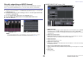
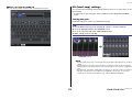
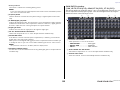
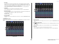
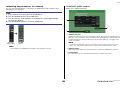
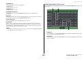
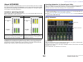
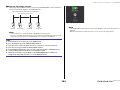
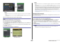
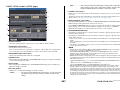
Centralogic section
Reference Manual
13
Centralogic section
The Centralogic section located below the touch screen lets you recall and simultaneously
control a set of eight input channels, output channels, or DCA groups. If you press one of the
Bank Select keys, the channels or DCA groups corresponding to that key will be assigned to
the Centralogic section, and can be controlled using the faders, [ON] keys, and [CUE] keys in
the Centralogic section.
Operations in the Centralogic section
NOTE
• When the SELECTED CHANNEL VIEW screen is displayed, you can switch to the OVERVIEW
screen by pressing any of the multifunction knobs 1-8. This is convenient when you want to
quickly switch to the OVERVIEW screen while leaving the same channels or DCA groups
selected for control.
• The bottom line of the OVERVIEW screen shows the channels or DCA groups that can be
controlled by the faders, [ON] keys and [CUE] keys of the Centralogic section.
• The top line of the OVERVIEW screen shows the channels that can be controlled by multifunction
knobs 1 - 8 in the Centralogic section.
Bank Select keys
STEP
1. Use the Bank Select keys in the Centralogic section to select the channels or DCA
groups that you want to control.
2. Use the faders and [ON] keys of the Centralogic section to adjust the level of the (up
to) eight selected channels and switch them on/off.
3. Use the fields on the OVERVIEW screen and the multifunction knobs to adjust the
parameters for the group of up to eight channels.

Centralogic section
Reference Manual
14
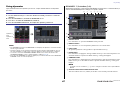
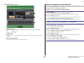
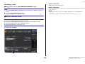
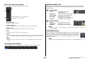
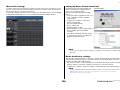
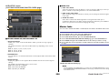
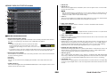
OVERVIEW Screen
CHANNEL NAME field
This field appears at the top and bottom of the screen and displays the channel number,
name, and icon for the currently-selected eight channels. The name of the currently-selected
channel is highlighted.
NOTE
If you have retained a specific channel (that is controlled by the faders or knobs in the Centralogic
section) by pressing and holding down the corresponding Bank Select key, the channel name
display at the top of the channel strip graphic may differ from the name displayed at the bottom
of the same channel strip.
GAIN/PATCH field
This field enables you to make HA (head amp) analog or digital gain settings. You can also
view the operational status of the head amp.
The view and the function of the controllers in this field vary depending on the type of the
selected channel.
If the head amp is patched:
1 GAIN knob
Sets the analog gain of the head amp.
• Press this field to assign the GAIN knob to the corresponding multifunction knob in the
Centralogic section, which enables you to adjust the gain. If the Gain Compensation
function is turned on, an indicator appears, showing the level of the signal output to
the audio network.
• If the GAIN knob has been assigned to a multifunction knob, press the knob to open
the GAIN/PATCH 8ch window.
2 OVER indicator
Lights when a signal at the input port or from the rack output exceeds the full scale level.
This indicator is available only if an input channel is selected.
3 +48V indicator
Indicates the phantom power (+48V) on or off status for the head amp. This indicator is
not displayed unless the head amp is patched to the channel.
4 Ø (Phase) indicator (input channels only)
Indicates the input phase setting for the head amp
NOTE
• If the slot is not connected to the head amp, the patch and the type of the MY card will be
displayed.
• If GAIN KNOB FUNCTION is set to DIGITAL GAIN in the PREFERENCE screen, the DIGITAL
GAIN knob will appear instead of knob
1, and indicator 3 will not be displayed.
• Press the SETUP button, then the USER SETUP button, select the PREFERENCE tab, and then
set the GAIN KNOB FUNCTION to DIGITAL GAIN. You will be able to adjust the digital gain value
by using the [TOUCH AND TURN] knob.
• You can also operate the digital gain by assigning INPUT GAIN DIGITAL GAIN to a USER
DEFINED knob, or by assigning an ALTERNATE function to a USER DEFINED key and then
adjusting the USER DEFINED knob or the GAIN knob for the selected channel while
ALTERNATE is on.
: Selected channel
: Unselected channel
1
4
3
2

Centralogic section
Reference Manual
15
If patched to a wireless mic (OVERVIEW screen)
1 RX.GAIN knob
Sets the gain for the receiver. Press the knob to open the GAIN/PATCH 1ch window.
• Press this field to assign the GAIN knob to the corresponding multifunction knob in the
Centralogic section, which enables you to adjust the gain.
• If the GAIN knob has been assigned to a multifunction knob, press the knob to open
the GAIN/PATCH 8ch window.
2 RF (Radio Frequency) signal meter
Shows bars to indicate the level of the RF signal. An active antenna indicator is shown
on the right side. It indicates which antenna is enabled.
NOTE
For more information about the relationship between the number of bars and the actual strength
of the RF signal, refer to the manual from Shure.
3 Battery indicator
Shows bars to indicate the remaining battery power.
NOTE
For more information about the relationship between the number of bars and maximum operation
time, refer to the manual from Shure.
4 OL indicator
Lights if the audio signal level of the receiver reaches the overload point.
NOTE
If the audio signal for the receiver is muted, 5 is displayed.
5 MUTE indicator
Displayed only if the audio signal for the receiver is muted.
NOTE
If the audio signal for the receiver is not muted, 4 is displayed.
INPUT DELAY field (input channels only)
This field displays the delay status for the input channel. Press this field to open the INPUT
DELAY 8ch window.
1 DELAY ON/OFF indicator
Indicates the on/off status of the delay.
INSERT/DIRECT OUT field
This field displays the Insert/Direct out status. Press this field to open the INSERT/DIRECT
OUT 8ch window.
1 INSERT ON/OFF indicator
Indicates the insert on/off status.
2 DIRECT OUT ON/OFF indicator (input channels only)
Indicates the Direct Out on/off status.
1 2
3 4 5
If the slot is patched:
The slot name will appear.
If the rack is connected:
The patch and module name will appear.
If the output is connected:
Only the patch will appear.
1
1
2

Centralogic section
Reference Manual
16
EQ field
This field graphically indicates the approximate response of
the EQ. Press this field to open the HPF/EQ 1ch window, in
which you can set the HPF and EQ.
NOTE
If DCA or monitor has been selected, this field will be blank.
DYNAMICS 1/2 field
This field displays the threshold value and meter for Dynamics
1/2. Press this field to open the DYNAMICS 1/2 1ch window.
NOTE
If DCA or monitor has been selected, this field will be blank.
SEND field
This field displays the send level, send on/off status, and pre/post
settings for 16 buses.
To select the 16 destination buses, use the [MIX 1-16] key/[MIX 17-24/
MATRIX] key in the SELECTED CHANNEL section.
To adjust the send level for each bus, use the SEND knob of the
SELECTED CHANNEL section
This field varies depending on the type of the destination bus.
If the destination bus is VARI (mono):
The knob color and scale color indicate the send on/off and pre/post
status. If the send is off, the knob color turns gray. With the post setting,
the knob scale color turns black.
If the destination bus is VARI (stereo):
If a pair of buses (odd-numbered and even-numbered) are in stereo, the
left-hand knob will function as the PAN knob, and the right-hand knob will
function as the SEND knob.
If the destination bus is set to FIXED:
The SEND ON/OFF button for each bus is shown instead of the knob.

Centralogic section
Reference Manual
17
TO STEREO/MONO field
This field displays the on/off status and pan/balance setting of the signal sent to the STEREO/
MONO bus.
This field varies depending on the type of the selected channel.
When an input channel or MIX channel is selected:
1 TO STEREO PAN knob
Sets the pan position of a signal routed to the STEREO bus.
Press the knob to open the STEREO/MONO 8ch window. If the ST IN channel is selected,
you can specify whether to view the PAN knob or the BALANCE knob in this window.
For a MIX channel, the PAN knob will appear if the signal is mono, and the BALANCE
knob will appear if the signal is stereo.
2 ST/MONO indicator
Indicates the status of a signal sent to the STEREO/MONO bus.
If an input or MIX channel is set to LCR mode, the LCR indicator
will be displayed.
When a MATRIX channel (monaural) or MONO channel is selected:
The Σ CLIP indicator will light if the signal is clipping at some point in the channel.
For a stereo MATRIX channel or STEREO channel, the BALANCE knob appears, indicating
the balance of the left/right channels.
DCA group field
A DCA group (1-16) to which the channel is assigned is displayed on the first or second row
in this field.
Press this field to open the DCA/MUTE GROUP ASSIGN MODE window.
Mute group field
A mute group (1-8) to which the channel is assigned is displayed on the third row in this field.
If the channel has been temporarily removed from the mute group, S (Safe) will appear on the
third row. If a dimmer level has been specified for a mute group, the color of the characters will
change from red to orange.
Press this field to open the DCA/MUTE GROUP ASSIGN MODE window.
1
2
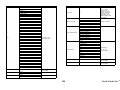
2

Input and output patching
Reference Manual
18
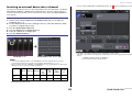
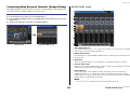
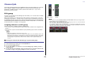
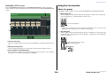
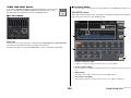
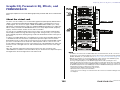
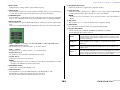
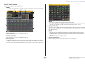
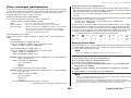
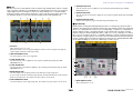
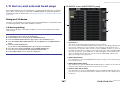
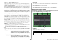
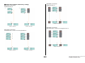
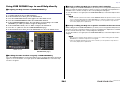
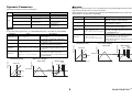
Input and output patching
This chapter explains how to edit the input patching and output patching, how to connect
inserts, and how to use direct outputs.
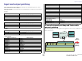
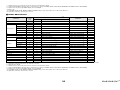
When the CL series is in the initial state, the following input ports (jacks/ports) are patched to
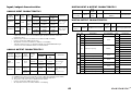
each input channel.
For CL5
For CL3
For CL1
When the CL is in the initial state, the output ports (jacks/ports) are patched to the following
output channels.
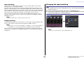
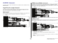
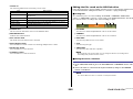
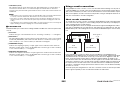
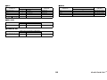
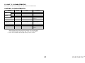
CL console internal patching and Dante audio
network patching
The following diagram shows the signal flow through the CL series console, I/O devices, and
Dante audio network.
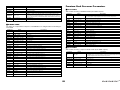
Input channels Input port (jack/port)
CH1-48 DANTE1-48
CH49-64 DANTE49-64
CH65-72 OMNI1-8
ST IN 1L-8R FX 1L(A)-FX 8R(B)
Input channels Input port (jack/port)
CH1-48 DANTE1-48
CH49-64 DANTE49-64
ST IN 1L-8R FX 1L(A)-FX 8R(B)
Input channels Input port (jack/port)
CH1-48 DANTE1-48
ST IN 1L-8R FX 1L(A)-FX 8R(B)
Output port (jack/port) Output channels
DANTE1-24 MIX 1-24
DANTE25-32 MATRIX1-8
DANTE33-34 STEREO L/R
DANTE35 MONO
DANTE36-37 MONITOR L/R
DANTE38 MONITOR C
DANTE39-40 CUE L/R
DANTE41-64 NO ASSIGN
SLOT1 (1)-(16) MIX1-16
SLOT2 (1)-(8) MIX17-24
SLOT2 (9)-(16) MATRIX1-8
SLOT3 (1)-(2) STEREO L/R
SLOT3(3) MONO
SLOT3 (4)-(5) MONITOR L/R
SLOT3(6) MONITOR C
SLOT3 (7)-(8) CUE L/R
SLOT3 (9)-(16) NO ASSIGN
OMNI OUT 1 - OMNI OUT 6 MIX 1-6
OMNI OUT 7 - OMNI OUT 8 STEREO L/R
FX1L(A), FX2L(A), FX3L(A),
FX4L(A), FX5L(A), FX6L(A),
FX7L(A), FX8L(A)
MIX17, MIX18, MIX19, MIX20, MIX21, MIX22, MIX23,
MIX24
DIGITAL OUT L/R STEREO L/R
RECORDER INPUT L/R STEREO L/R
Output port (jack/port) Output channels
8 16 16 16 64
SW
Dante-MY16-AUD
ID #3
ID #1
ID #2
OMNI MY MY MY
INPUT PATCH
Dante Network
“Dante” (ports)
CL series
I/O Device
Dante
patching
CL series
internal
patching
I/O Device
I/O Device

Input and output patching
Reference Manual
19
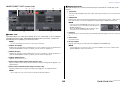
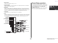
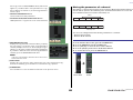
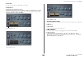
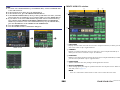
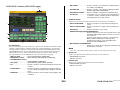
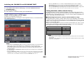
Input patching
CL series consoles and I/O devices feature two types of patching: Dante audio network
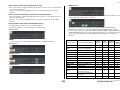
patching and CL console internal patching.
For Dante audio network patching, you will use the DANTE INPUT PATCH window. In this
window, you can patch the CL console and I/O device inputs. Sixty-four (64) channels can be
input from a Dante audio network to a CL series console. You can choose up to 64 channels
from a maximum of 512 channels (logical value) of Dante audio network signals. Select the I/
O device (up to 64 channels) that you want to control from the CL series console.
Then, route the input signals (that were patched in the DANTE INPUT PATCH screen) to
channels on the CL series console. To do this, choose input ports from DANTE 1-64 in the
GAI N /PATCH s c re e n .
NOTE
By default, DANTE 1-64 are assigned to input channels 1-64.
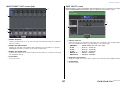
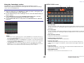
Output patching
Use the OUTPUT PORT screen to patch the CL console’s output channels and Dante audio
network. In this window, assign output channel signals to DANTE 1-64 ports.
NOTE
By default, MIX 1 - 24 are assigned to DANTE 1 - 24, MATRIX 1 - 8 are assigned to DANTE 25
- 32, STEREO L/R are assigned to DANTE 33/34, and MONO is assigned to DANTE 35.
Next, patch the output signals from DANTE 1-64 (assigned in the OUTPUT PORT SETUP
screen) to I/O rack outputs. Use the OUTPUT PATCH screen of the I/O RACK to make these
assignments.
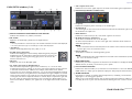
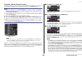
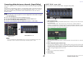
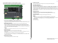
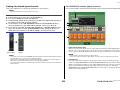
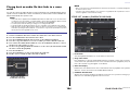
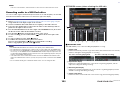
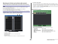
Changing the input patching
NOTE
You can also select an input port from the GAIN/PATCH screen.
STEP
1.
Use the Bank Select keys in the Centralogic section to select the input channels that
you want to control.
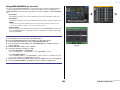
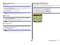
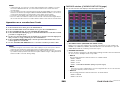
2. Press the channel number/channel name field on the OVERVIEW screen.
3. Select the type of port in the category select list on the PATCH/NAME screen, and
use the port select buttons to select the input port.
OVERVIEW screen PATCH/NAME screen

Input and output patching
Reference Manual
20
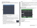
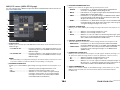
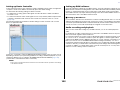
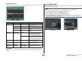
PATCH/NAME screen
1 PATCH button
Indicates the currently-selected input port. If you press this button when selecting an
icon or changing the channel name, you will return to the input port select screen.
2 Icon button
Indicates the icon that is selected for the corresponding channel. When you press this
button, a screen will appear in which you can select an icon or sample name.
3 Channel name input box
Indicates the name that is assigned to the corresponding channel. When you press this
field, a keyboard window allowing you to change the channel name will appear.
4 Category select list
Selects the category of input port. The categories correspond to the following input
ports. The displayed categories vary depending on the channel type.
• DANTE1-32 ............DANTE1 - DANTE32
• DANTE33-64..........DANTE33 - DANTE64
• OMNI/PB OUT .......OMNI 1 - OMNI 8, PB OUT (L), PB OUT (R)
• SLOT1 ....................SLOT1(1) - SLOT1(16)
• SLOT2 ....................SLOT2(1) - SLOT2(16)
• SLOT3 ....................SLOT3(1) - SLOT3(16)
• EFFECT RACK ......FX1L(A) - FX8R(B)
• PREMIUM RACK...PR1L(A) - PR2R(B)
5 Port select buttons
Select the input port that is assigned to the currently-selected channel.
6 Tabs
Enable you to switch between items.
7 Close button
Closes the screen.
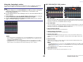
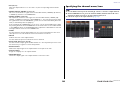
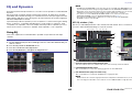
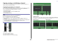
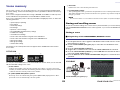
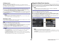
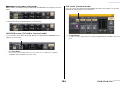
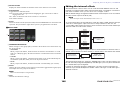
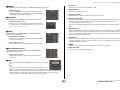
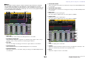
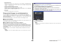
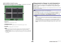
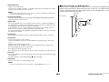
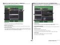
Changing the output patching
To change the patching, you can either select the output port that will be the output destination
of each output channel, or you can select the output channel that will be the output source for
each output port.
Selecting the output port for each output channel
2 73
1
6
4
5
STEP
1. Use the Bank Select keys in the Centralogic section to select the output channels.
2. Press the channel number/channel name field on the OVERVIEW screen.
3. Select the type of port in the category select list on the PATCH/NAME screen, and
use the port select buttons to select the output port.
OVERVIEW screen PATCH/NAME screen
Pagina se încarcă...
Pagina se încarcă...
Pagina se încarcă...
Pagina se încarcă...
Pagina se încarcă...
Pagina se încarcă...
Pagina se încarcă...
Pagina se încarcă...
Pagina se încarcă...
Pagina se încarcă...
Pagina se încarcă...
Pagina se încarcă...
Pagina se încarcă...
Pagina se încarcă...
Pagina se încarcă...
Pagina se încarcă...
Pagina se încarcă...
Pagina se încarcă...
Pagina se încarcă...
Pagina se încarcă...
Pagina se încarcă...
Pagina se încarcă...
Pagina se încarcă...
Pagina se încarcă...
Pagina se încarcă...
Pagina se încarcă...
Pagina se încarcă...
Pagina se încarcă...
Pagina se încarcă...
Pagina se încarcă...
Pagina se încarcă...
Pagina se încarcă...
Pagina se încarcă...
Pagina se încarcă...
Pagina se încarcă...
Pagina se încarcă...
Pagina se încarcă...
Pagina se încarcă...
Pagina se încarcă...
Pagina se încarcă...
Pagina se încarcă...
Pagina se încarcă...
Pagina se încarcă...
Pagina se încarcă...
Pagina se încarcă...
Pagina se încarcă...
Pagina se încarcă...
Pagina se încarcă...
Pagina se încarcă...
Pagina se încarcă...
Pagina se încarcă...
Pagina se încarcă...
Pagina se încarcă...
Pagina se încarcă...
Pagina se încarcă...
Pagina se încarcă...
Pagina se încarcă...
Pagina se încarcă...
Pagina se încarcă...
Pagina se încarcă...
Pagina se încarcă...
Pagina se încarcă...
Pagina se încarcă...
Pagina se încarcă...
Pagina se încarcă...
Pagina se încarcă...
Pagina se încarcă...
Pagina se încarcă...
Pagina se încarcă...
Pagina se încarcă...
Pagina se încarcă...
Pagina se încarcă...
Pagina se încarcă...
Pagina se încarcă...
Pagina se încarcă...
Pagina se încarcă...
Pagina se încarcă...
Pagina se încarcă...
Pagina se încarcă...
Pagina se încarcă...
Pagina se încarcă...
Pagina se încarcă...
Pagina se încarcă...
Pagina se încarcă...
Pagina se încarcă...
Pagina se încarcă...
Pagina se încarcă...
Pagina se încarcă...
Pagina se încarcă...
Pagina se încarcă...
Pagina se încarcă...
Pagina se încarcă...
Pagina se încarcă...
Pagina se încarcă...
Pagina se încarcă...
Pagina se încarcă...
Pagina se încarcă...
Pagina se încarcă...
Pagina se încarcă...
Pagina se încarcă...
Pagina se încarcă...
Pagina se încarcă...
Pagina se încarcă...
Pagina se încarcă...
Pagina se încarcă...
Pagina se încarcă...
Pagina se încarcă...
Pagina se încarcă...
Pagina se încarcă...
Pagina se încarcă...
Pagina se încarcă...
Pagina se încarcă...
Pagina se încarcă...
Pagina se încarcă...
Pagina se încarcă...
Pagina se încarcă...
Pagina se încarcă...
Pagina se încarcă...
Pagina se încarcă...
Pagina se încarcă...
Pagina se încarcă...
Pagina se încarcă...
Pagina se încarcă...
Pagina se încarcă...
Pagina se încarcă...
Pagina se încarcă...
Pagina se încarcă...
Pagina se încarcă...
Pagina se încarcă...
Pagina se încarcă...
Pagina se încarcă...
Pagina se încarcă...
Pagina se încarcă...
Pagina se încarcă...
Pagina se încarcă...
Pagina se încarcă...
Pagina se încarcă...
Pagina se încarcă...
Pagina se încarcă...
Pagina se încarcă...
Pagina se încarcă...
Pagina se încarcă...
Pagina se încarcă...
Pagina se încarcă...
Pagina se încarcă...
Pagina se încarcă...
Pagina se încarcă...
Pagina se încarcă...
Pagina se încarcă...
Pagina se încarcă...
Pagina se încarcă...
Pagina se încarcă...
Pagina se încarcă...
Pagina se încarcă...
Pagina se încarcă...
Pagina se încarcă...
Pagina se încarcă...
Pagina se încarcă...
Pagina se încarcă...
Pagina se încarcă...
Pagina se încarcă...
Pagina se încarcă...
Pagina se încarcă...
Pagina se încarcă...
Pagina se încarcă...
Pagina se încarcă...
Pagina se încarcă...
Pagina se încarcă...
Pagina se încarcă...
Pagina se încarcă...
Pagina se încarcă...
Pagina se încarcă...
Pagina se încarcă...
Pagina se încarcă...
Pagina se încarcă...
Pagina se încarcă...
Pagina se încarcă...
Pagina se încarcă...
Pagina se încarcă...
Pagina se încarcă...
Pagina se încarcă...
Pagina se încarcă...
Pagina se încarcă...
Pagina se încarcă...
Pagina se încarcă...
Pagina se încarcă...
Pagina se încarcă...
Pagina se încarcă...
Pagina se încarcă...
Pagina se încarcă...
Pagina se încarcă...
Pagina se încarcă...
Pagina se încarcă...
Pagina se încarcă...
Pagina se încarcă...
Pagina se încarcă...
Pagina se încarcă...
Pagina se încarcă...
Pagina se încarcă...
Pagina se încarcă...
Pagina se încarcă...
Pagina se încarcă...
Pagina se încarcă...
Pagina se încarcă...
Pagina se încarcă...
Pagina se încarcă...
Pagina se încarcă...
Pagina se încarcă...
Pagina se încarcă...
Pagina se încarcă...
Pagina se încarcă...
Pagina se încarcă...
Pagina se încarcă...
Pagina se încarcă...
Pagina se încarcă...
Pagina se încarcă...
Pagina se încarcă...
Pagina se încarcă...
Pagina se încarcă...
Pagina se încarcă...
Pagina se încarcă...
Pagina se încarcă...
Pagina se încarcă...
Pagina se încarcă...
Pagina se încarcă...
Pagina se încarcă...
Pagina se încarcă...
Pagina se încarcă...
Pagina se încarcă...
Pagina se încarcă...
Pagina se încarcă...
Pagina se încarcă...
Pagina se încarcă...
Pagina se încarcă...
Pagina se încarcă...
Pagina se încarcă...
Pagina se încarcă...
Pagina se încarcă...
Pagina se încarcă...
Pagina se încarcă...
Pagina se încarcă...
Pagina se încarcă...
Pagina se încarcă...
Pagina se încarcă...
Pagina se încarcă...
Pagina se încarcă...
Pagina se încarcă...
Pagina se încarcă...
Pagina se încarcă...
Pagina se încarcă...
Pagina se încarcă...
Pagina se încarcă...
Pagina se încarcă...
Pagina se încarcă...
Pagina se încarcă...
Pagina se încarcă...
Pagina se încarcă...
Pagina se încarcă...
Pagina se încarcă...
Pagina se încarcă...
Pagina se încarcă...
Pagina se încarcă...
Pagina se încarcă...
Pagina se încarcă...
Pagina se încarcă...
Pagina se încarcă...
Pagina se încarcă...
Pagina se încarcă...
Pagina se încarcă...
Pagina se încarcă...
Pagina se încarcă...
Pagina se încarcă...
Pagina se încarcă...
Pagina se încarcă...
Pagina se încarcă...
Pagina se încarcă...
Pagina se încarcă...
Pagina se încarcă...
Pagina se încarcă...
Pagina se încarcă...
Pagina se încarcă...
Pagina se încarcă...
Pagina se încarcă...
Pagina se încarcă...
Pagina se încarcă...
Pagina se încarcă...
Pagina se încarcă...
Pagina se încarcă...
Pagina se încarcă...
Pagina se încarcă...
Pagina se încarcă...
Pagina se încarcă...
Pagina se încarcă...
Pagina se încarcă...
Pagina se încarcă...
Pagina se încarcă...
Pagina se încarcă...
Pagina se încarcă...
Pagina se încarcă...
Pagina se încarcă...
Pagina se încarcă...
Pagina se încarcă...
Pagina se încarcă...
Pagina se încarcă...
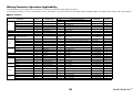
-
 1
1
-
 2
2
-
 3
3
-
 4
4
-
 5
5
-
 6
6
-
 7
7
-
 8
8
-
 9
9
-
 10
10
-
 11
11
-
 12
12
-
 13
13
-
 14
14
-
 15
15
-
 16
16
-
 17
17
-
 18
18
-
 19
19
-
 20
20
-
 21
21
-
 22
22
-
 23
23
-
 24
24
-
 25
25
-
 26
26
-
 27
27
-
 28
28
-
 29
29
-
 30
30
-
 31
31
-
 32
32
-
 33
33
-
 34
34
-
 35
35
-
 36
36
-
 37
37
-
 38
38
-
 39
39
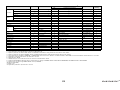
-
 40
40
-
 41
41
-
 42
42
-
 43
43
-
 44
44
-
 45
45
-
 46
46
-
 47
47
-
 48
48
-
 49
49
-
 50
50
-
 51
51
-
 52
52
-
 53
53
-
 54
54
-
 55
55
-
 56
56
-
 57
57
-
 58
58
-
 59
59
-
 60
60
-
 61
61
-
 62
62
-
 63
63
-
 64
64
-
 65
65
-
 66
66
-
 67
67
-
 68
68
-
 69
69
-
 70
70
-
 71
71
-
 72
72
-
 73
73
-
 74
74
-
 75
75
-
 76
76
-
 77
77
-
 78
78
-
 79
79
-
 80
80
-
 81
81
-
 82
82
-
 83
83
-
 84
84
-
 85
85
-
 86
86
-
 87
87
-
 88
88
-
 89
89
-
 90
90
-
 91
91
-
 92
92
-
 93
93
-
 94
94
-
 95
95
-
 96
96
-
 97
97
-
 98
98
-
 99
99
-
 100
100
-
 101
101
-
 102
102
-
 103
103
-
 104
104
-
 105
105
-
 106
106
-
 107
107
-
 108
108
-
 109
109
-
 110
110
-
 111
111
-
 112
112
-
 113
113
-
 114
114
-
 115
115
-
 116
116
-
 117
117
-
 118
118
-
 119
119
-
 120
120
-
 121
121
-
 122
122
-
 123
123
-
 124
124
-
 125
125
-
 126
126
-
 127
127
-
 128
128
-
 129
129
-
 130
130
-
 131
131
-
 132
132
-
 133
133
-
 134
134
-
 135
135
-
 136
136
-
 137
137
-
 138
138
-
 139
139
-
 140
140
-
 141
141
-
 142
142
-
 143
143
-
 144
144
-
 145
145
-
 146
146
-
 147
147
-
 148
148
-
 149
149
-
 150
150
-
 151
151
-
 152
152
-
 153
153
-
 154
154
-
 155
155
-
 156
156
-
 157
157
-
 158
158
-
 159
159
-
 160
160
-
 161
161
-
 162
162
-
 163
163
-
 164
164
-
 165
165
-
 166
166
-
 167
167
-
 168
168
-
 169
169
-
 170
170
-
 171
171
-
 172
172
-
 173
173
-
 174
174
-
 175
175
-
 176
176
-
 177
177
-
 178
178
-
 179
179
-
 180
180
-
 181
181
-
 182
182
-
 183
183
-
 184
184
-
 185
185
-
 186
186
-
 187
187
-
 188
188
-
 189
189
-
 190
190
-
 191
191
-
 192
192
-
 193
193
-
 194
194
-
 195
195
-
 196
196
-
 197
197
-
 198
198
-
 199
199
-
 200
200
-
 201
201
-
 202
202
-
 203
203
-
 204
204
-
 205
205
-
 206
206
-
 207
207
-
 208
208
-
 209
209
-
 210
210
-
 211
211
-
 212
212
-
 213
213
-
 214
214
-
 215
215
-
 216
216
-
 217
217
-
 218
218
-
 219
219
-
 220
220
-
 221
221
-
 222
222
-
 223
223
-
 224
224
-
 225
225
-
 226
226
-
 227
227
-
 228
228
-
 229
229
-
 230
230
-
 231
231
-
 232
232
-
 233
233
-
 234
234
-
 235
235
-
 236
236
-
 237
237
-
 238
238
-
 239
239
-
 240
240
-
 241
241
-
 242
242
-
 243
243
-
 244
244
-
 245
245
-
 246
246
-
 247
247
-
 248
248
-
 249
249
-
 250
250
-
 251
251
-
 252
252
-
 253
253
-
 254
254
-
 255
255
-
 256
256
-
 257
257
-
 258
258
-
 259
259
-
 260
260
-
 261
261
-
 262
262
-
 263
263
-
 264
264
-
 265
265
-
 266
266
-
 267
267
-
 268
268
-
 269
269
-
 270
270
-
 271
271
-
 272
272
-
 273
273
-
 274
274
-
 275
275
-
 276
276
-
 277
277
-
 278
278
-
 279
279
-
 280
280
-
 281
281
-
 282
282
-
 283
283
-
 284
284
-
 285
285
-
 286
286
-
 287
287
-
 288
288
-
 289
289
-
 290
290
-
 291
291
-
 292
292
-
 293
293
-
 294
294
-
 295
295
-
 296
296
-
 297
297
-
 298
298
-
 299
299
-
 300
300
-
 301
301
-
 302
302
-
 303
303
-
 304
304
-
 305
305
-
 306
306
-
 307
307
-
 308
308
-
 309
309
-
 310
310
-
 311
311
-
 312
312
-
 313
313
-
 314
314
-
 315
315
-
 316
316
-
 317
317
-
 318
318
-
 319
319
-
 320
320
-
 321
321
-
 322
322
-
 323
323
-
 324
324


în alte limbi
- Türkçe: Yamaha CL1 Kullanım kılavuzu
- français: Yamaha CL1 Manuel utilisateur
- čeština: Yamaha CL1 Uživatelský manuál
- русский: Yamaha CL1 Руководство пользователя
- English: Yamaha CL1 User manual
- suomi: Yamaha CL1 Ohjekirja
- polski: Yamaha CL1 Instrukcja obsługi
- Deutsch: Yamaha CL1 Benutzerhandbuch
- italiano: Yamaha CL1 Manuale utente
- español: Yamaha CL1 Manual de usuario
- svenska: Yamaha CL1 Användarmanual
- dansk: Yamaha CL1 Brugermanual
- português: Yamaha CL1 Manual do usuário
- Nederlands: Yamaha CL1 Handleiding
Lucrări înrudite
-
Yamaha CL1 Manual de utilizare
-
Yamaha V3 Manual de utilizare
-
Yamaha QL1 Manual de utilizare
-
Yamaha QL1 Manual de utilizare
-
-
-
-
-
-