Yamaha RX-V740RDS Manualul proprietarului
- Categorie
- Receptoare AV
- Tip
- Manualul proprietarului

YAMAHA ELECTRONICS CORPORATION, USA 6660 ORANGETHORPE AVE., BUENA PARK, CALIF. 90620, U.S.A.
YAMAHA CANADA MUSIC LTD. 135 MILNER AVE., SCARBOROUGH, ONTARIO M1S 3R1, CANADA
YAMAHA ELECTRONIK EUROPA G.m.b.H. SIEMENSSTR. 22-34, 25462 RELLINGEN BEI HAMBURG, F.R. OF GERMANY
YAMAHA ELECTRONIQUE FRANCE S.A. RUE AMBROISE CROIZAT BP70 CROISSY-BEAUBOURG 77312 MARNE-LA-VALLEE CEDEX02, FRANCE
YAMAHA ELECTRONICS (UK) LTD. YAMAHA HOUSE, 200 RICKMANSWORTH ROAD WATFORD, HERTS WD1 7JS, ENGLAND
YAMAHA SCANDINAVIA A.B. J A WETTERGRENS GATA 1, BOX 30053, 400 43 VÄSTRA FRÖLUNDA, SWEDEN
YAMAHA MUSIC AUSTRALIA PTY, LTD. 17-33 MARKET ST., SOUTH MELBOURNE, 3205 VIC., AUSTRALIA
Printed in Malaysia WA69370
RX-V740RDS
GB
OWNER’S MANUAL
MODE D’EMPLOI
BEDIENUNGSANLEITUNG
BRUKSANVISNING
MANUALE DI ISTRUZIONI
MANUAL DE INSTRUCCIONES
GEBRUIKSAANWIJZING
RX-V740RDS
AV Receiver
Ampli-tuner audio-vidéo
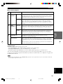
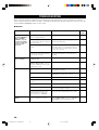
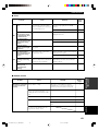
TECHNISCHE GEGEVENS
AUDIO GEDEELTE
• Minimum RMS uitgangsvermogen voor hoofd, midden, achter,
midden achter
20 Hz t/m 20 kHz, 0,06% THV, 8 Ω ..................................... 90 W
1 kHz, 0,7% THV, 8 Ω ........................................................ 110 W
• DIN Standaard uitgangsvermogen
[Model voor Europa]
1 kHz, 0,7% THV, 4 Ω ........................................................ 140 W
• IEC uitgangsvermogen
[Modellen voor het V.K., Europa en Singapore]
1 kHz, 0,06% THV, 8 Ω ...................................................... 105 W
• Maximum uitgangsvermogen (EIAJ)
[Modellen voor China, Korea en algemene modellen]
1 kHz, 10% THV, 8 Ω ......................................................... 130 W
• Dynamisch uitgangsvermogen (IHF) 8/6/4/2 Ω
[Modellen voor de VS en Canada] ................. 130/160/190/235 W
[Overige modellen] ......................................... 120/145/185/230 W
• Dempingsfactor
20 Hz t/m 20 kHz, 8 Ω ................................................ 100 of meer
• Frequentierespons
CD naar Hoofd L/R .............................. 10 Hz t/m 100 kHz, –3 dB
• Totale Harmonische Vervorming
20 Hz t/m 20 kHz, 45 W, 8 Ω, Hoofd L/R ............................ 0,06%
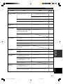
• Signaal-ruis verhouding (IHF-A Netwerk)
PHONO MM naar OUT (REC) (kortgesloten 5 mV)
[Modellen voor de VS, Canada, China, Korea en algemene
modellen] ........................................................................... 86 dB
[Overige modellen] ............................................................ 81 dB
CD (kortgesloten 250 mV) naar Hoofd L/R, Effect uit ...... 100 dB
• Residuele ruis (IHF-A Netwerk)
Hoofd L/R ......................................................... 150 µV of minder
• Kanaalscheiding (1 kHz/10 kHz)
CD (5,1 kΩ getermineerd) naar Hoofd L/R .............. 60 dB/45 dB
• Toonregeling (Hoofd L/R)
BASS versterking/verzwakking .............................. ±10 dB/50 Hz
TREBLE versterking/verzwakking ....................... ±10 dB/20 kHz
• Uitgangsvermogen hoofdtelefoon ............................. 150 mV/100 Ω
• Ingangsgevoeligheid
CD, etc .................................................................... 150 mV/47 kΩ
6CH INPUT ............................................................ 150 mV/47 kΩ
• Uitgangsniveau
OUT (REC) ........................................................... 150 mV/1,2 kΩ
OUTPUT MAIN/CENTER/REAR CENTER/
REAR (SURROUND) ............................................ 2,4 V/1,2 kΩ
OUTPUT SUBWOOFER ............................................. 4 V/1,2 kΩ
ZONE 2 [modellen voor de VS, Canada en Australië]
............................................................................ 150 mV/1,5 kΩ
VIDEO GEDEELTE
• Videosignaal-type ....................................................... NTSC of PAL
• Signaal-ruis verhouding .......................................................... 50 dB
• Frequentierespons (MONITOR OUT)
Composiet, S-Video ............................... 5 Hz t/m 10 MHz, –3 dB
Component ............................................. 5 Hz t/m 30 MHz, –3 dB
FM GEDEELTE
• Afstembereik
[Modellen voor de VS en Canada] ................ 87,5 t/m 107,9 MHz
[Overige modellen] .................................... 87,50 t/m 108,00 MHz
• 50 dB Rustgevoeligheid (IHF, 100% mod.)
Mono/Stereo ........................ 2,0 µV (17,3 dBf) /25 µV (39,2 dBf)
• Bruikbare gevoeligheid (IHF, mono) .................... 1,0 µV (11,2 dBf)
• Signaal-ruis verhouding (IHF)
Mono/Stereo .............................................................. 76 dB/70 dB
• Harmonische vervorming (1 kHz)
Mono/Stereo ................................................................. 0,2%/0,3%
• Stereoscheiding (1 kHz) .......................................................... 42 dB
• Frequentierespons ............................. 20 Hz t/m 15 kHz +0,5, –2 dB
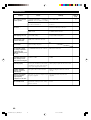
AM GEDEELTE
• Afstembereik ........................................ 530/531 t/m 1710/1611 kHz
• Bruikbare gevoeligheid .................................................... 300 µV/m
ALGEMEEN
• Stroomvoorziening
[Modellen voor de VS en Canada] ...... 120 V wisselstroom/60 Hz
[Model voor Australië] ........................ 240 V wisselstroom/50 Hz
[Modellen voor het V.K., Europa en Singapore]
.......................................................... 230 V wisselstroom/50 Hz
[Model voor Korea] ............................. 220 V wisselstroom/60 Hz
[Modellen voor China en algemene modellen]
............................... 110/120/220/240 V wisselstroom, 50/60 Hz
• Stroomverbruik
[Modellen voor de VS en Canada] ......................... 320 W/420 VA
[Overige modellen] .............................................................. 320 W
Standby-stand ........................................................ ongeveer 0,9 W
• Netstroom-aansluitingen
[Modellen voor de VS, Canada, Europa en Singapore]
......................................................... 2 (maximum totaal 100 W)
[Modellen voor China en algemene modellen]
........................................................... 2 (maximum totaal 50 W)
[Modellen voor het V.K. en Australië] .......... 1 (maximum 100 W)
• Afmetingen (b x h x d) ..................................... 435 x 171 x 390 mm
• Gewicht.................................................................................. 13,0 kg
* Technische gegevens kunnen zonder voorafgaande kennisgeving
gewijzigd worden.
0100RX-V740_cv-GB.p65 03.2.10, 9:45 AM1

1 To assure the finest performance, please read this
manual carefully. Keep it in a safe place for future
reference.
2 Install this sound system in a well ventilated, cool,
dry, clean place — away from direct sunlight, heat
sources, vibration, dust, moisture, and/or cold.
Allow ventilation space of at least 30 cm on the top,
20 cm on the left and right, and 20 cm on the back
of this unit.
3 Locate this unit away from other electrical
appliances, motors, or transformers to avoid
humming sounds.
4
Do not expose this unit to sudden temperature
changes from cold to hot, and do not locate this unit
in a environment with high humidity (i.e. a room with
a humidifier) to prevent condensation inside this unit,
which may cause an electrical shock, fire, damage to
this unit, and/or personal injury.
5 Avoid installing this unit where foreign object may
fall onto this unit and/or this unit may be exposed
to liquid dripping or splashing. On the top of this
unit, do not place:
– Other components, as they may cause damage
and/or discoloration on the surface of this unit.
–
Burning objects (i.e. candles), as they may cause
fire, damage to this unit, and/or personal injury.
– Containers with liquid in them, as they may fall
and liquid may cause electrical shock to the
user and/or damage to this unit.
6 Do not cover this unit with a newspaper, tablecloth,
curtain, etc. in order not to obstruct heat radiation.
If the temperature inside this unit rises, it may
cause fire, damage to this unit, and/or personal
injury.
7 Do not plug in this unit to a wall outlet until all
connections are complete.
8 Do not operate this unit upside-down. It may
overheat, possibly causing damage.
9 Do not use force on switches, knobs and/or cords.
10 When disconnecting the power cord from the wall
outlet, grasp the plug; do not pull the cord.
11 Do not clean this unit with chemical solvents; this
might damage the finish. Use a clean, dry cloth.
12 Only voltage specified on this unit must be used.
Using this unit with a higher voltage than specified
is dangerous and may cause fire, damage to this
unit, and/or personal injury. YAMAHA will not be
held responsible for any damage resulting from use
of this unit with a voltage other than specified.
13
To prevent damage by lightning, disconnect the power
cord from the wall outlet during an electrical storm.
14 Do not attempt to modify or fix this unit. Contact
qualified YAMAHA service personnel when any
service is needed. The cabinet should never be
opened for any reasons.
CAUTION: READ THIS BEFORE OPERATING YOUR UNIT.
15 When not planning to use this unit for long periods
of time (i.e. vacation), disconnect the AC power
plug from the wall outlet.
16 Be sure to read the “TROUBLESHOOTING” section
on common operating errors before concluding that
this unit is faulty.
17 Before moving this unit, press STANDBY/ON to set
this unit in standby mode, and disconnect the AC
power plug from the wall outlet.
18
VOLTAGE SELECTOR (China and General models only)
The VOLTAGE SELECTOR on the rear panel of this
unit must be set for your local main voltage
BEFORE plugging into the AC main supply.
Voltages are 110/120/220/240 V AC, 50/60 Hz.
This unit is not disconnected from the AC power
source as long as it is connected to the wall outlet,
even if this unit itself is turned off. This state is called
standby mode. In this state, this unit is designed to
consume a very small quantity of power.
WARNING
TO REDUCE THE RISK OF FIRE OR ELECTRIC
SHOCK, DO NOT EXPOSE THIS UNIT TO RAIN
OR MOISTURE.
■ For U.K. customers
If the socket outlets in the home are not suitable for the
plug supplied with this appliance, it should be cut off and
an appropriate 3 pin plug fitted. For details, refer to the
instructions described below.
Note
• The plug severed from the mains lead must be destroyed, as a
plug with bared flexible cord is hazardous if engaged in a live
socket outlet.
■ Special Instructions for U.K. Model
IMPORTANT
THE WIRES IN MAINS LEAD ARE COLOURED
IN ACCORDANCE WITH THE FOLLOWING
CODE:
Blue: NEUTRAL
Brown: LIVE
As the colours of the wires in the mains lead of this
apparatus may not correspond with the coloured
markings identifying the terminals in your plug,
proceed as follows:
The wire which is coloured BLUE must be connected
to the terminal which is marked with the letter N or
coloured BLACK. The wire which is coloured
BROWN must be connected to the terminal which is
marked with the letter L or coloured RED.
Making sure that neither core is connected to the earth
terminal of the three pin plug.
CAUTION
0101RX-V740_Cau_E-GB.p65 03.2.12, 4:21 PM2

1
English
INTRODUCTION
PREPARATION
BASIC
OPERATION
ADVANCED
OPERATION
ADDITIONAL
INFORMATION
CONTENTS
INTRODUCTION
CONTENTS ............................................................ 1
FEATURES ............................................................. 2
GETTING STARTED ............................................ 3
Supplied accessories .................................................. 3
Installing batteries in the remote control ................... 3
CONTROLS AND FUNCTIONS ......................... 4
Front panel................................................................. 4
Remote control .......................................................... 6
Front panel display .................................................... 8
ADVANCED OPERATION
SET MENU ........................................................... 41
Set menu list ............................................................ 41
Adjusting the items on the set menu ....................... 41
SOUND 1 SPEAKER SET
(speaker mode settings) ....................................... 42
SOUND 2 SP DISTANCE (speaker distance) ........ 44
SOUND 3 LFE LEVEL .......................................... 44
SOUND 4 D. RANGE (dynamic range) ................. 44
SOUND 5 CENTER GEQ
(center graphic equalizer) .................................... 45
SOUND 6 HP TONE CTRL
(headphone tone control) .................................... 45
INPUT 1 I/O ASSIGN (input/output assignment) .. 45
INPUT 2 INPUT MODE (initial input mode) ........ 46
INPUT 3 INPUT RENAME .................................... 46
OPTION 1 DISPLAY SET ...................................... 46
OPTION 2 MEM. GUARD (memory guard) ......... 47
OPTION 3 AUDIO MUTE ..................................... 47
OPTION 4 ZONE SET ........................................... 47
REMOTE CONTROL FEATURES ................... 48
Control area ............................................................. 48
Setting the manufacturer code ................................. 49
Changing the source name in the display window .. 50
Clearing renamed source names, and setup
manufacturer codes ............................................. 51
Controlling other components ................................. 52
SETTING THE SPEAKER LEVELS ................ 53
Adjusting the volume during playback ................... 53
Using the test tone ................................................... 53
PREPARATION
CONNECTIONS .................................................... 9
Before connecting components ................................. 9
Connecting video components ................................ 10
Connecting audio components ................................ 12
Connecting the antennas.......................................... 13
Connecting an external amplifier ............................ 14
Connecting an external decoder .............................. 14
Connecting the speakers .......................................... 15
Connecting the power supply cords ........................ 18
Turning on the power .............................................. 18
ON-SCREEN DISPLAY (OSD) .......................... 19
BASIC SYSTEM SETTINGS ............................. 20
Using the basic menu .............................................. 20
Setting the unit to match your speaker system ........ 22
Setting speaker output levels (SP LEVEL) ............. 22
BASIC OPERATION
PLAYBACK .......................................................... 23
Input modes and indications .................................... 25
Selecting a sound field program .............................. 26
DIGITAL SOUND FIELD PROCESSING (DSP)
............................................................................ 29
Understanding sound fields ..................................... 29
Hi-Fi DSP programs ................................................ 29
CINEMA-DSP ...................................................... 30
Sound design of CINEMA-DSP ............................. 30
CINEMA-DSP Programs ........................................ 30
Sound field effects ................................................... 32
TUNING ................................................................ 33
Presetting stations .................................................... 34
Selecting a preset station ......................................... 36
RECEIVING RDS STATIONS ........................... 37
Description of RDS data ......................................... 37
Changing the RDS mode ......................................... 37
PTY SEEK function ................................................ 38
EON function .......................................................... 38
SLEEP TIMER ..................................................... 39
RECORDING ....................................................... 40
ADDITIONAL INFORMATION
SOUND FIELD PROGRAM PARAMETER
EDITING .......................................................... 54
What is a sound field? ............................................. 54
Sound field program parameters ............................. 54
Changing parameter settings ................................... 55
Digital Sound Field Parameter Descriptions ........... 56
TROUBLESHOOTING ....................................... 60
GLOSSARY .......................................................... 64
SPECIFICATIONS .............................................. 66
0102RX-V740_01-08_EN-GB.P65 03.2.12, 4:22 PM1

2
Manufactured under license from Dolby Laboratories.
“Dolby”, “Pro Logic”, and the double-D symbol are
trademarks of Dolby Laboratories.
FEATURES
Other features
◆ 96 kHz/24-bit D/A converter
◆ Set menu for optimizing this unit for your Audio/
Video system
◆ Test tone generator for easier speaker balance
adjustment
◆ 6-channel external decoder input
◆ On screen display function helpful in controlling this
unit
◆ Component video input/output capability
◆ S-video signal input/output capability
◆ Optical and coaxial digital audio signal jacks
◆ Video Conversion (Composite Video ⇔ S Video)
◆ Sleep timer
◆ Remote control with preset manufacturer codes
◆ Zone B capability
“DTS”, “DTS-ES Extended Surround” and “Neo:6” are
trademarks of Digital Theater System, Inc.
Built-in 6-channel power amplifier
◆ Minimum RMS output power
(0.06% THD, 20 Hz – 20 kHz, 8Ω)
Main: 90 W + 90 W
Center: 90 W
Rear: 90 W + 90 W
Rear center: 90 W
Multi-mode digital sound field processing
◆ Dolby Pro Logic/Dolby Pro Logic II decoder
◆ Dolby Digital/Dolby Digital EX decoder
◆ DTS/DTS-ES Matrix 6.1, Discrete 6.1, DTS Neo:6
Decoder
◆ CINEMA DSP: Combination of YAMAHA DSP
technology and Dolby Pro Logic, Dolby Digital or
DTS
◆ Virtual CINEMA DSP
◆ SILENT CINEMA DSP
Sophisticated AM/FM Tuner
◆ 40-Station random access preset tuning
◆ Automatic preset tuning
◆ Preset station shifting capability (Preset editing)
■ About this manual
• y indicates a tip for your operation.
• Some operations can be performed by using either the buttons on the main unit or on the remote control. In cases
when the button names differ between the main unit and the remote control, the button name on the remote control is
given in parentheses.
• This manual is printed prior to production. Design and specifications are subject to change in part for the reason of
the improvement in operativity ability, and others. In this case, the product has priority.
0102RX-V740_01-08_EN-GB.P65 03.2.12, 4:22 PM2

3
English
INTRODUCTION
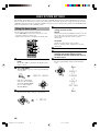
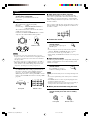
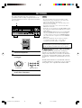
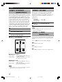
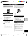
Installing batteries in the remote
control
Insert the batteries in the correct direction by aligning the
+ and – marks on the batteries with the polarity markings
(+ and –) inside the battery compartment.
1 Press the part marked with a and slide off
the battery compartment cover.
2 Insert the four batteries supplied (AAA, R03,
UM-4) according to the polarity markings on
the inside of the battery compartment.
3 Slide the cover back on so that it snaps into
place.
■ Notes on batteries
• Change all of the batteries if you notice a decrease in
the operating range of the remote control, that the
indicator does not flash, or the light becoming dim.
• Do not use old batteries together with new ones.
• Do not use different types of batteries (such as alkaline
and manganese batteries) together. Read the packaging
carefully as these different types of batteries may have
the same shape and color.
• If the batteries have leaked, dispose of them
immediately. Avoid touching the leaked material or
letting it come into contact with clothing, etc. Clean the
battery compartment thoroughly before installing new
batteries.
If the remote control is without batteries for more than
2 minutes, or if exhausted batteries remain in the
remote control, the contents of the memory may be
cleared. When the memory is cleared, insert new
batteries, set up the manufacturer code and program
any acquired functions that may have been cleared.
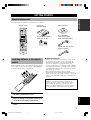
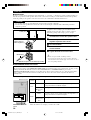
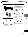
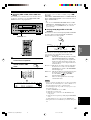
AM loop antenna
(Europe, U.K., Australia and
Singapore models)
Indoor FM antenna
(U.S.A., Canada, China,
Korea and General models)
Batteries (4)
(AAA, R03, UM-4)
Remote control
GETTING STARTED
Supplied accessories
After unpacking, check that the following parts are contained.
75-ohm/300-ohm antenna
adapter (U.K. model)
DISC SKIP
TRANSMIT
RE
-
NAME
CLEAR
CODE SET
SYSTEM
POWER
STANDBY
6CH INPUT
SLEEP
A
PHONO
V
-
AUX
D
-
TV/CBL VCR 1 VCR2/DVR DVD
TUNER
MD
/
CD-R
CD
CB
SELECT
POWER
TV
AMP
REC
AUDIO
VOL
TV INPUT
SET MENU
A/B/C/D/E
LEVEL
TITLE
TV VOL
TV VOL
TV MUTE
SELECT
MENU
MUTE
CH
TEST
ON SCREEN
STEREO
EFFECT
DISPLAYRETURN
CH
PRESET PRESET
HALL JAZZ CLUB
ROCK
CONCERT
ENTER-
TAINMENT
MUSIC
VIDEO
TV
THEATER
MOVIE
THEATER 1
MOVIE
THEATER 2
/DTS
SUR.
1234
5678
9101112
NIGHT
6.1/5.1
0
CHP/INDEX
+
10
POWER
AV
1
2
3
0102RX-V740_01-08_EN-GB.P65 03.2.12, 4:22 PM3

4
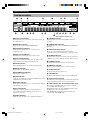
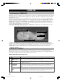
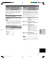
CONTROLS AND FUNCTIONS
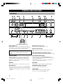
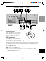
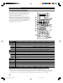
Front panel
1 STANDBY/ON
Turns the unit on, or sets it in standby mode. When you
turn the unit on, you will hear a click and there will be a 4
to 5-second delay before it can reproduce sound.
Standby mode
In this mode, the unit uses a small amount of power in
order to receive infrared-signals from the remote
control.
2 INPUT MODE
Sets the priority for the types of input signals (AUTO,
DTS, ANALOG) received when one component is
connected to two or more input jacks. You cannot set
priority for an audio source if you have selected 6CH
INPUT as the input source.
3 INPUT
Selects the input source you want to listen to or watch.
4 6CH INPUT
Selects the audio source connected to the 6CH INPUT
jacks. This selection takes priority over sources selected
with INPUT (or the input selector buttons on the remote
control).
5 Remote control sensor
Receives signals from the remote control.
6 Front panel display
Shows information about the operational status of the
unit.
7 TUNING MODE (AUTO/MAN’L MONO)
Switches the tuning mode between automatic and manual.
8 PRESET/TUNING (EDIT)
Switches the function of PRESET/TUNING l / h
between selecting a preset station number and tuning (the
colon (:) turns on or off).
This button is also used to exchange the assignment of
two preset stations with each other.
9 FM/AM
Switches the reception band between FM and AM.
0 MEMORY (MAN’L/AUTO FM)
Stores the current station in memory.
q VOLUME
Controls the output level of all audio channels.
This does not affect the OUT (REC) level.
(U.K. and Europe models only)
INPUT
AUTO/MANUAL MONO
MAN`L/AUTO FM
TUNING MODE MEMORY
EDIT
PRESET/TUNING
FM/AM
OPTICALRAUDIOLVIDEOS VIDEO
EFFECT
PRESET/TUNING
A/B/C/D/E
PROGRAMSTEREOSPEAKERS
BA
6CH INPUTINPUT MODE
MODE START
RDS MODE/FREQ
PTY SEEK
EON
SILENT
PHONES
TREBLE
VOLUME
BASS
VIDEO AUX
STANDBY
/ON
NEXT SET MENU
1 32 4 8756 q90
epo
t iu
a s fd
MODE START
RDS MODE/FREQ
PTY SEEK
EON
w r y
0102RX-V740_01-08_EN-GB.P65 03.2.12, 4:22 PM4

5
English
INTRODUCTION
w SILENT (PHONES jack)
Allows you to enjoy DSP effects when listening with
headphones. When you connect headphones to the
headphone jack, no signals are output to the speakers or
the OUTPUT jacks.
e SPEAKERS A/B
Turns the set of main speakers connected to the A and/or
B terminals on or off.
r STEREO/EFFECT
Switches between normal stereo and DSP effect
reproduction. When you select STEREO, the unit mixes
down all Dolby Digital and DTS signals (except the LFE
channel) as well as those 2-channel signals without
effects, to the main left and right speakers.
t PROGRAM l / h
Select the DSP program.
y A/B/C/D/E
Selects preset station groups A to E when the unit is in
tuner mode.
NEXT
Selects the set menu mode when the unit is not in tuner
mode.
u PRESET/TUNING l / h
Select preset station numbers 1 to 8 when a colon (:) is
displayed in the front panel display.
Select the tuning frequency when a colon (:) is not
displayed when the unit is in tuner mode.
SET MENU –/+
Adjust settings on the set menu when the unit is not in
tuner mode.
i VIDEO AUX jacks
Inputs for audio and video signals from a portable
external source (game console, etc.). Set the input source
to V-AUX to select source signals from these jacks.
o BASS
Adjusts the low-frequency response for the main left and
right channels.
Turn right to increase or left to decrease the low-
frequency response.
p TREBLE
Adjusts the high-frequency response for the main left and
right channels.
Turn right to increase or left to decrease the high-
frequency response.
(U.K. and Europe models only)
a RDS MODE/FREQ
Press this button when the unit is receiving an RDS
station, to cycle the display mode among PS mode,
PTY mode, RT mode, CT mode (if the station offers
those RDS data service) and/or frequency display
mode in turn.
s PTY SEEK MODE
Press this button to set the unit in the PTY SEEK
mode.
d PTY SEEK START
Press this button to begin searching for a station after
the desired program type has been selected in the PTY
SEEK mode.
f EON
Press this button to select a radio program type
(NEWS, INFO, AFFAIRS, SPORT) to tune in
automatically.
CONTROLS AND FUNCTIONS
0102RX-V740_01-08_EN-GB.P65 03.2.12, 4:22 PM5

6
DISC SKIP
TRANSMIT
RE
-
NAME
CLEAR
CODE SET
SYSTEM
POWER
STANDBY
6CH INPUT
SLEEP
A
PHONO
V
-
AUX
D
-
TV/CBL VCR 1 VCR2/DVR DVD
TUNER
MD
/
CD-R
CD
CB
SELECT
POWER
TV
AMP
REC
AUDIO
VOL
TV INPUT
SET MENU
A/B/C/D/E
LEVEL
TITLE
TV VOL
TV VOL
TV MUTE
SELECT
MENU
MUTE
CH
TEST
ON SCREEN
STEREO
EFFECT
DISPLAYRETURN
CH
PRESET PRESET
HALL JAZZ CLUB
ROCK
CONCERT
ENTER-
TAINMENT
MUSIC
VIDEO
TV
THEATER
MOVIE
THEATER 1
MOVIE
THEATER 2
/DTS
SUR.
1234
5678
9101112
NIGHT
6.1/5.1
0
CHP/INDEX
+
10
POWER
AV
o
p
f
d
g
i
9
0
8
q
2
3
4
1
5
7
6
w
e
r
t
y
u
a
s
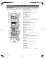
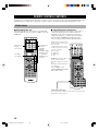
Remote control
1 Infrared window
Outputs infrared control signals. Aim this window at the
component you want to operate.
2 TRANSMIT indicator
Flashes while the remote control is sending signals.
3 STANDBY
Sets the unit in standby mode.
4 SYSTEM POWER
Turns on the power of the unit.
5 Å/ı/Ç
Sets the remote control to operate other components (not
necessarily connected to this unit) without changing this
unit’s input source.
6 Input selector buttons
Select the input source and set the remote control to
operate the selected source component.
7 Display window
Shows the source component you are currently
controlling.
8 LEVEL
Selects the effect speaker channel to adjust.
9 Multi control section
Used to change and implement settings.
0 TEST
Outputs a test tone for use when adjusting the speaker
levels.
q DSP program
Select DSP programs when the remote control is in AMP
mode. Press one of these buttons repeatedly to select a
DSP program within a program group.
w RE-NAME
Used to change the input source name in the display
window.
e CLEAR
Used to clear functions acquired using the rename
features, and to set manufacturer codes.
r CODE SET
Used to set up manufacturer codes (see page 49).
t SLEEP
Sets the sleep timer.
y 6CH INPUT
Selects the audio source connected to the 6CH INPUT
jacks.
This section describes the controls and functions of the
remote control. Make sure that the AMP mode is selected
before use.
CONTROLS AND FUNCTIONS
0102RX-V740_01-08_EN-GB.P65 03.2.12, 4:22 PM6

7
English
INTRODUCTION
Approximately 6 m (20 feet)
u SELECT k/n
Set the remote to control a component other than the one
selected with the input selector buttons.
i AMP
Switches the function of the same controls between AMP
and the component selected using the input selector
buttons.
o VOL +/–
Increase or decrease the volume level.
p MUTE
Mutes the sound. Press again to restore the audio output
to the previous volume level.
a SET MENU
Selects the set menu mode.
s ON SCREEN
Displays the input or operation status on the on-screen
display.
d STEREO/EFFECT
Switches between normal stereo and DSP effect
reproduction. When you select STEREO the unit mixes
down all Dolby Digital and DTS signals (except the LFE
channel) as well as those 2-channel signals without effect
sounds, to the main left and right speakers.
f 6.1/5.1
Switches the Dolby Digital EX or DTS ES decoder on or
off.
g NIGHT
Sets the unit in night listening mode.
■ Using the remote control
The remote control transmits a directional infrared beam.
Be sure to aim the remote control directly at the remote
control sensor on the main unit during operation.
■ Handling the remote control
• Do not spill water or other liquids on the remote
control.
• Do not drop the remote control.
• Do not leave or store the remote control in the
following types of conditions:
– high humidity or temperature such as near a heater,
stove or bath;
– dusty places; or
– in places subject to extremely low temperatures.
INPUT
AUTO/MANUAL MONO
MAN`L/AUTO FM
TUNING MODE MEMORY
EDIT
PRESET/TUNING FM/AM
OPTICALRAUDIOLVIDEOS VIDEO
EFFECT
PRESET/TUNING
SET MENU
A/B/C/D/E
NEXT
PROGRAMSTEREOSPEAKERS
BA
6CH INPUTINPUT MODE
SILENT
PHONES
TREBLE
VOLUME
BASS
VIDEO AUX
STANDBY
/ON
CODE SET
30° 30°
CONTROLS AND FUNCTIONS
0102RX-V740_01-08_EN-GB.P65 03.2.12, 4:22 PM7

8
V-AUXVCR1
VCR2/DVR
D-TV/CBL
DVD
MD/CD-R
TUNER CD PHONO
DISCRETEMATRIX
DIGITAL
PL
PL
EX
PCM
ES
SILENT
DSP
HiFi
NIGHT
VIRTUAL
A B
SP
AUTO
STEREO
SLEEP
VOLUME
MUTE
MEMORYTUNED
L C R
RLLFE RC RR
~~~~~~~~~~~~~~
dB
ft
m
S
CTRTPTYPS
HOLDPTYEON
13
45
8
7
6
2
90qw yer uiop
a
s
t
1 Processor indicators
The indicators for the various decoders light up when the
decoders are in use.
2 VIRTUAL indicator
Lights up when using Virtual CINEMA DSP.
3 Headphones indicator
Lights up when headphones are connected to the
headphone jack.
4 Input source indicator
Highlights the current input source with a cursor.
5 Sound field indicator
Displays the sound field management the unit is using
when you listen to a DSP sound field program.
6 AUTO indicator
Shows that this unit is in the automatic tuning mode.
7 MUTE indicator
Flashes while the MUTE function is on.
8 VOLUME level indicator
Indicates the volume level.
9 PCM indicator
Lights up when this unit is reproducing PCM (pulse code
modulation) digital audio signals.
0 SILENT indicator
Lights up when headphones are connected and the digital
sound field processor is on.
q SP A B indicator
Lights up to indicate which set of main speakers is
selected. Both indicators light up when both sets of
speakers are selected.
w NIGHT indicator
Lights up when the unit is set to night listening mode.
e HiFi DSP indicator
Lights up when you select a Hi-Fi DSP sound field
program.
r CINEMA DSP indicator
Lights up when you select a CINEMA DSP sound field
program.
t Multi-information display
Shows the current DSP program name and other
information when you are adjusting or changing settings.
y STEREO indicator
Lights up when the unit is receiving a strong signal from
a FM stereo broadcast while the “AUTO” indicator is lit.
u TUNED indicator
Lights up when this unit is tuned to a radio station.
i MEMORY indicator
Flashes to show a station can be stored in memory.
o SLEEP indicator
Lights up while the sleep timer is on.
p LFE indicator
Lights up when the input signal contains an LFE signal.
a Input channel indicator
The indicators for the appropriate sound channels light up
when a digital signal from a source is played back.
s RDS indicator (U.K. and Europe models only)
The name(s) of the RDS data offered by the currently
received RDS station light(s) up.
EON indicator lights up when an RDS station that offers
the EON data service is being received.
PTY HOLD indicator lights up while searching for
stations in the PTY SEEK mode.
Front panel display
(U.K. and Europe models only)
CONTROLS AND FUNCTIONS
0102RX-V740_01-08_EN-GB.P65 03.2.12, 4:22 PM8

9
English
PREPARATION
PHONO
R
L
B
A
MAIN
REAR
(SURROUND)
REAR
CENTER
CENTERR L
CENTER
SUB
WOOFER
6CH INPUT
DIGITAL
OUTPUT
SIGNAL
GND
DIGITAL
INPUT
VIDEOAUDIOAUDIO
1
2
3
4
5
MD/CD-R
MD/CD-R
DVD
D-TV/CBL
OPTICAL
OPTICAL
COAXIAL
VCR-1
OUT
IN
MONITOR OUT
OUT
VCR 2
/DVR
IN
DVD
D-TV
/CBL
MD
/CD-R
OUT
(REC)
IN
(PLAY)
SURROUND
MAIN
CD
CD
S VIDEOVIDEO
S VIDEOVIDEO
R
L
TUNER
75Ω UNBAL.
FM
ANT
GND
AM
ANT
R
L
CENTER
SUB
WOOFER
REAR
CENTER
REAR
(SURROUND
)
MAIN
OUTPUT
P
R
DVD
A
P
B
Y
COMPORNENT VIDEO
SPEAKERS
R L
D-TV
/CBL
B
MONITOR
OUT
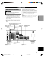
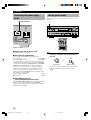
CONNECTIONS
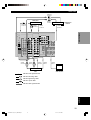
Before connecting components
CAUTION
Do not connect this unit or other components to the
mains power until all connections between the
components have been completed.
• Be sure all connections are made correctly, that is to
say L (left) to L, R (right) to R, “+” to “+” and “–” to
“–”. Some components require different connection
methods and have different jack names. Refer to the
operation instructions for each component you wish to
connect to this unit.
• After you have completed all connections, check them
again to make sure they are correct.
• The jack names correspond to the names on the input
selector.
■ Connecting to digital jacks
This unit has digital jacks for direct transmission of
digital signals through either coaxial or fiber optic cables.
You can use the digital jacks to input PCM, Dolby Digital
and DTS bitstreams. Use digital connections if you wish
to enjoy the multi-channel sound track of DVD material,
etc. with DSP effects. All digital input jacks are
acceptable for 96 kHz sampling digital signals.
Note
• The OPTICAL jacks on this unit conform to the EIA standard.
If you use a fiber optic cable that does not conform to this
standard this unit may not function properly.
AC OUTLETS
(page 18)
6CH INPUT jacks
(page 14)
DIGITAL OUTPUT jack
(page 12)
OUTPUT jacks
(page 14)
DIGITAL INPUT jacks
(pages 9 – 12)
Antenna input terminals
(page 13)
Speaker terminals
(page 17)
Video component jacks
(pages 10 – 11)
Audio component jacks
(page 12)
SUBWOOFER OUTPUT
jack (page 17)
This jack is reserved for factory use. Do not
connect any equipment to this jack.
0103RX-V740_09-19_EN-GB.p65 03.2.12, 4:23 PM9

10
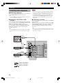
Connecting video components
Refer to the connection examples on the next page.
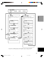
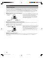
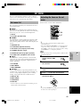
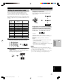
■ Types of video jacks
1 VIDEO jack
Conventional composite video signal.
2 S VIDEO jack
Transmits color and luminance separately and
achieves high-quality color reproduction.
3 COMPONENT VIDEO jacks
Transmit color difference (P
B, PR) and luminance
separately and provide the best quality picture.
Use the commercially available cable type specified for
connecting each jack.
y
• Signals received through the S VIDEO input jacks can be
converted to composite signals in this unit and output through
its VIDEO MONITOR OUT as well.
• (With the exception of China and General models) Signals
received through the VIDEO jack on this unit can be output
through the S VIDEO MONITOR OUT jack by setting “V
CONV.” in “OPTION 1 DISPLAY SET” on the set menu to
ON.
• When the unit receives signals through both S VIDEO and
VIDEO jacks, signals input through the S VIDEO jack have
priority.
• You can designate the input for the COMPONENT VIDEO A
and B jacks to suit your components by using “INPUT 1 I/O
ASSIGNMENT” on the set menu.
■ Connecting a video monitor
Connect the video input jack on your video monitor to the
MONITOR OUT VIDEO jack.
Note
• If you connect this unit with a source component using
Component video jacks, you also need to connect your video
monitor using Component video jacks.
■ Connecting a DVD player/digital TV/cable
TV
Connect the optical digital audio signal output jack on
your component to the DIGITAL INPUT jack and
connect the video signal output jack on the component to
the VIDEO jack on this unit.
y
• Use the AUDIO jacks on this unit for a video component
which does not have optical digital output jack. However,
multi-channel reproduction cannot be obtained with audio
signals input from the AUDIO jacks.
■ Connecting a recording component
Connect the audio signal input jacks on your video
component to the AUDIO OUT jacks on this unit. Then
connect the video signal input jack on the video
component to the VIDEO OUT jack on this unit for
picture recording.
Connect the audio signal output jacks on your component
to the AUDIO IN jacks on this unit. Then connect the
video signal output jack on the component to the VIDEO
IN jack on this unit to play a source from your recording
component.
A second VCR or DVD recorder can be connected using
the VCR 2/DVR jacks.
Note
• Once you have connected a recording component to this unit,
keep its power turned on while using this unit. If the power is
off, this unit may distort the sound from other components.
COMPONENT VIDEO
P
R
P
B
Y
S VIDEOVIDEO
1 2 3
S VIDEO
VIDEO
COMPONENT
VIDEO
Only when “V CONV.” in “OPTION 1 DISPLAY
SET” is set to ON on the set menu.
Output
(MONITOR OUT)
Signal flow inside this unit
Input
CONNECTIONS
0103RX-V740_09-19_EN-GB.p65 03.2.12, 4:23 PM10

11
English
PREPARATION
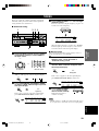
indicates video signal direction
indicates optical cables
indicates right analog cables
indicates left analog cables
indicates audio signal direction
Video monitorVCR
DVD player
TV/digital TV/
cable TV
PHONO
R
L
B
A
MAIN
R
CENTER
SUB
WOOFER
6CH INPUT
DIGITAL
OUTPUT
SIGNAL
GND
DIGITAL
INPUT
VIDEOAUDIOAUDIO
1
2
3
4
5
MD/CD-R
MD/CD-R
DVD
D-TV/CBL
OPTICAL
OPTICAL
COAXIAL
VCR-1
OUT
IN
MONITOR OUT
OUT
VCR 2
/DVR
IN
DVD
D-TV
/CBL
MD
/CD-R
OUT
(REC)
IN
(PLAY)
SURROUND
MAIN
CD
CD
S VIDEOVIDEO
S VIDEOVIDEO
R
L
TUNER
75Ω UNBAL.
FM
ANT
GND
AM
ANT
R
L
REA
R
CENT
E
REAR
(SURROUND
)
MAIN
OUTPUT
P
R
DVD
A
P
B
Y
COMPORNENT VIDEO
D-TV
/CBL
B
MONITOR
OUT
AUDIO
OUTPUT
AUDIO
INPUT
LR LR
VIDEO
INPUT
VIDEO
OUTPUT
O
OPTICAL
OUTPUT
AUDIO
OUTPUT
L R
VIDEO
OUTPUT
VIDEO
OUTPUT
O
OPTICAL
OUTPUT
AUDIO
OUTPUT
L
R
VIDEO
INPUT
O
L
R
CONNECTIONS
0103RX-V740_09-19_EN-GB.p65 03.2.12, 4:23 PM11

12
PHONO
R
L
CENTER
SUB
WOOFER
6CH INPUT
DIGITAL
OUTPUT
SIGNAL
GND
DIGITAL
INPUT
VIDEOAUDIOAUDIO
1
2
3
4
5
MD/CD-R
MD/CD-R
DVD
D-TV/CBL
OPTICAL
OPTICAL
COAXIAL
VCR-1
OUT
IN
MONITOR OUT
OUT
VCR 2
/DVR
IN
DVD
D-TV
/CBL
MD
/CD-R
OUT
(REC)
IN
(PLAY)
SURROUND
MAIN
CD
CD
S VIDEOVIDEO
S VIDEOVIDEO
R
L
TUNER
75Ω UNBAL.
FM
ANT
GND
AM
ANT
P
R
DVD
A
P
B
COMPORNENT V
D-TV
/CBL
B
MONITOR
OUT
OPTICAL
INPUT
OPTICAL
OUTPUT
O
O
GND
OUTPUT
L
R
COAXIAL
OUTPUT
C
O
C
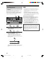
Connecting audio components
■ Connecting a CD player
Connect the coaxial digital output jack on your CD player
to the DIGITAL INPUT CD jack on this unit.
y
• Use the AUDIO jacks on this unit for a CD player which does
not have coaxial digital output jack.
■ Connecting a CD recorder or MD
recorder
Connect the optical digital signal input jack on your CD
recorder or MD recorder to the DIGITAL OUTPUT MD/
CD-R jack on this unit for digital recording.
Connect the optical digital output jack on your CD
recorder or MD recorder to the DIGITAL INPUT MD/
CD-R jack on this unit to play a source from your
recording component.
y
• Use the AUDIO jacks on this unit for a CD recorder or MD
recorder which does not have optical digital input or output
jack.
indicates signal direction
Turntable
CD player
Notes
• Once you have connected a recording component to this unit,
keep its power turned on while using this unit. If the power is
off, this unit may distort the sound from other components.
• The DIGITAL OUTPUT jack and analog OUT (REC) jacks
are independent. The DIGITAL OUTPUT jack only outputs
digital signals, while the OUT (REC) jacks output analog
signals only.
■ Connecting a turntable
Connect the output jacks on your turntable to the PHONO
jacks on this unit.
PHONO jacks are for connecting a turntable with an MM
or high-output MC cartridge. If you have a turntable with
a low-output MC cartridge, use an in-line boosting
transformer or MC-head amplifier when connecting to
these jacks.
y
• Connect your turntable to the GND terminal to reduce noise in
the signal. Please note that this connection may increase noise
with some record players.
indicates coaxial cables
indicates optical cables
CD recorder or
MD recorder
CONNECTIONS
0103RX-V740_09-19_EN-GB.p65 03.2.12, 4:23 PM12

13
English
PREPARATION
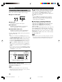
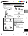
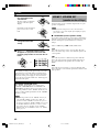
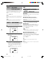
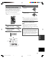
■ Connecting the AM loop antenna
1 Set up the AM loop antenna, then connect it
to the terminals on this unit.
2 Press and hold the tab to insert the AM loop
antenna lead wires into the AM ANT and
GND terminals.
3 Orient the AM loop antenna for the best
reception.
Notes
• The AM loop antenna should be placed away from this unit.
• The AM loop antenna should always be connected, even if an
outdoor AM antenna is connected to this unit.
A properly installed outdoor antenna provides clearer
reception than an indoor one. If you experience poor
reception quality, an outdoor antenna may improve the
quality. Consult the nearest authorized YAMAHA
dealer or service center about the outdoor antennas.
FREQUENCY STEP switch (China and General
models only)
Because the inter-station frequency
spacing differs in different areas, set the
FREQUENCY STEP switch (located on
the rear panel) according to the frequency
spacing in your area.
North, Central and South America:
100 kHz/10 kHz
Other areas: 50 kHz/9 kHz
Before setting this switch, disconnect the
AC power plug of this unit from the AC
outlet.
100kHz/10kHz
FREQUENCY
STEP
50kHz/9kHz
FM/AM
Ground (GND terminal)
For maximum safety and minimum
interference, connect the antenna GND
terminal to a good earth ground. A good
earth ground is a metal stake driven into
moist earth.
Indoor FM
antenna
(included)
AM loop antenna
(included)
Connecting the antennas
Open the cover of the
included 75-ohm/300-ohm
antenna adapter.
Cut the external sleeve
of the 75-ohm coaxial
cable and prepare it for
connection.
Cut the lead wire and
remove it.
Insert the cable wire into the
slot, and clamp it with pliers.
Snap the cover into
place.
12
Unit:
mm (inch)
3
Lead wire
4
Clamp with
pliers.
Clamp
with
pliers.
Insert the wire
into the slot.
5
75-ohm/300-ohm antenna adapter (U.K. model only)
11 (7/16)
8 (5/16)
6 (1/14)
TUNER
75Ω UNBAL.
FM
ANT
GND
AM
ANT
Both AM and FM indoor antennas are included with this
unit. In general, these antennas should provide sufficient
signal strength.
Connect each antenna correctly to the designated
terminals.
CONNECTIONS
0103RX-V740_09-19_EN-GB.p65 03.2.12, 4:23 PM13

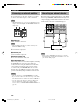
14
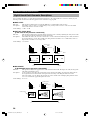
Connecting an external amplifier
If you want to increase the power output to the speakers,
or want to use another amplifier, connect an external
amplifier to the OUTPUT jacks as follows.
Note
• When RCA pin plugs are connected to the OUTPUT jacks for
output to an external amplifier, the SPEAKERS terminals also
output signals.
1 MAIN jacks
Main channel line output jacks.
Note
• The signals output through these jacks are affected by the
BASS and TREBLE settings.
2 REAR (SURROUND) jacks
Rear channel line output jacks.
3 CENTER jack
Center channel line output jack.
4 REAR CENTER jack
Rear center channel line output jack.
5 SUBWOOFER jack
When using a subwoofer with built-in amplifier, including
the YAMAHA Active Servo Processing Subwoofer
System, connect the input jack of the subwoofer system
to this jack. Low bass signals distributed from the main,
center and/or rear channels are directed to this jack in
accordance with your SPEAKER SET selections. The
unit also directs the LFE (low-frequency effect) signals
generated when Dolby Digital or DTS is decoded to this
jack based on your SPEAKER SET selections.
Notes
• The cut-off frequency of the SUBWOOFER jack is 90 Hz.
• If you do not use a subwoofer, allocate the signals to the main
left and right speakers by changing the settings of “SOUND 1
SPEAKER SET” item “1E BASS” on the set menu.
• Use the control on the subwoofer to adjust its volume level.
You can also adjust the volume level by using this unit’s
remote control (see “SETTING THE SPEAKER LEVELS” on
page 53).
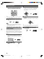
Connecting an external decoder
This unit is equipped with 6 additional input jacks (MAIN
left and right, CENTER, SURROUND left and right and
SUBWOOFER) for discrete multi-channel input from a
component equipped with a multi-channel decoder and 6
channel output jacks such as a DVD/SACD player.
Note
• When you select 6CH INPUT as the input source, the unit
automatically turns off the digital sound field processor, and
you cannot use DSP programs.
R
L
CENTER
SUB
WOOFER
REAR
CENTER
REAR
(SURROUND
)MAIN
OUTPUT
12 3
45
CONNECTIONS
CENTER
SUB
WOOFER
6CH INPUT
MONITOR OUT
OUT
VCR 2
/DVR
IN
SURROUND
MAIN
S VIDEOVIDEO
L R LR
CENTER
SUBWOOFER MAIN
SURROUND
DVD/SACD player
0103RX-V740_09-19_EN-GB.p65 03.2.12, 4:23 PM14

15
English
PREPARATION
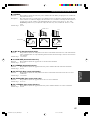
■ Speaker placement
Refer to the following diagram when you place the
speakers.
Main speakers
Place the main left and right speakers an equal distance
from the ideal listening position. The distance between
each speaker and each side of the video monitor should
also be the same.
Center speaker
Align the front face of the center speaker with the front
face of your video monitor. Place the speaker as close to
the monitor as possible (such as directly over or under the
monitor) and centrally between the main speakers.
Rear speakers
Place these speakers behind your listening position,
facing slightly inwards, about 1.8 m (6 feet) above the
floor.
Rear center speaker
Place the rear center speaker in the center between the
rear left and right speakers at the same height from the
floor as the rear speakers.
Subwoofer
The position of the subwoofer is not so critical, because
low bass sounds are not highly directional. However, it is
better to place the subwoofer near the main speakers.
Turn it slightly toward the center of the room to reduce
wall reflections.
Note
• If you do not use any of effect speakers (rear, center and/or
rear center), change the settings of “SOUND 1 SPEAKER
SET” items at the set menu to direct signals to other terminals
you have connected speakers to.
CAUTION
Use magnetically shielded speakers. If these speakers
still create interference with the monitor, place the
speakers away from the monitor.
Connecting the speakers
■ Speakers
This unit has been designed to provide the best sound-
field quality with a 6-speaker system, using main left and
right speakers, rear left and right speakers, a center
speaker, and a rear center speaker. If you use different
brands of speakers (with different tonal qualities) in your
system, the tone of a moving human voice and other types
of sound may not shift smoothly. We recommend that you
use speakers from the same manufacturer or speakers
with the same tonal quality.
The main speakers are used for the main source sound
plus effect sounds. They will probably be the speakers
from your present stereo system. The rear speakers are
used for effect and surround sounds. The center speaker is
for the center sounds (dialog, vocals, etc.). The rear center
speaker supplements the rear (left and right) speakers and
provides for more realistic front-to-back transitions.
The main speakers should be high-performance models
and have enough power-handling capacity to accept the
maximum output of your audio system. The other
speakers do not have to be equal to the main speakers. For
precise sound localization, however, it is ideal to use the
models of equivalent performance with the main
speakers.
Use of a subwoofer expands your sound field
It is also possible to further expand your system with the
addition of a subwoofer. The use of a subwoofer is
effective not only for reinforcing bass frequencies from
any or all channels, but also for reproducing the LFE
(low-frequency effect) channel with high fidelity when
playing back Dolby Digital or DTS signals. The
YAMAHA Active Servo Processing Subwoofer System is
ideal for natural and lively bass reproduction.
Main
speaker (L)
1.8 m (6 feet)
Rear speaker (L)
Rear center
speaker
Rear speaker (R)
Subwoofer
Main speaker (R)
Center speaker
CONNECTIONS
0103RX-V740_09-19_EN-GB.p65 03.2.12, 4:23 PM15

16
■ Connections
Be sure to connect the left channel (L), right channel (R), “+” (red) and “–” (black) in accordance with the markers on
this unit, the speakers, and the speaker cables. If the connections are faulty, no sound will be heard from the speakers,
and if the polarity of the speaker connections is incorrect, the sound will be unnatural and lack bass.
CAUTION
• Use speakers with the specified impedance shown on the rear panel of this unit.
• Do not let the bare speaker wires touch each other or any metal part of this unit. This could damage this unit
and/or the speakers.
10 mm (3/8”)
Red: positive (+)
Black: negative (–)
Banana plug
(With the exception of U.K. and Europe models)
CONNECTIONS
A speaker cord is actually a pair of insulated cables
running side by side. One cable is colored or shaped
differently, perhaps with a stripe, groove or ridge.
1 Remove approximately 10 mm (3/8”) of
insulation from each of the speaker cables.
2 Twist the exposed wires of the cable
together to prevent short circuits.
3 Unscrew the knob.
4 Insert one bare wire into the hole in the side
of each terminal.
5 Tighten the knob to secure the wire.
y
(With the exception of U.K. and Europe models)
• You can also use banana plug connectors. First, tighten the
knob and then insert the banana plug connector into the end of
the corresponding terminal.
12
MAIN
CENTER
REAR CENTER
REAR
A OR B :
A+B :
:
:
:
4ΩMIN.
8ΩMIN.
6ΩMIN.
6ΩMIN.
6ΩMIN.
/SPEAKER
/SPEAKER
/SPEAKER
/SPEAKER
/SPEAKER
IMPEDANCE SELECTOR
SET BEFORE POWER ON
MAIN
CENTER
REAR CENTER
REAR
A OR B :
A+B :
:
:
:
8ΩMIN.
16ΩMIN.
8ΩMIN.
8ΩMIN.
8ΩMIN.
/SPEAKER
/SPEAKER
/SPEAKER
/SPEAKER
/SPEAKER
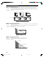
■ IMPEDANCE SELECTOR switch
WARNING
Do not change setting of the IMPEDANCE SELECTOR switch when the unit power is switched on, as doing so may
damage the unit. If this unit fails to turn on when STANDBY/ON (or SYSTEM POWER) is pressed, the
IMPEDANCE SELECTOR switch may not be fully slid to either position. If this is the case, slide the switch all the
way to either position when this unit is in standby mode. Be sure to move this switch only when this unit is in
standby mode.
Select the switch position (left or right) according to the impedance of the speakers in your system.
4
3
5
IMPEDANCE SELECTOR
switch
(General model)
Switch
position
Left
Right
Speaker
Main
Center,
Rear Center,
Rear
Main*
Center,
Rear Center,
Rear
Impedance level
If you use one/two set(s) of main speakers, the impedance of
each speaker must be 4 Ω/8 Ω or higher.
The impedance of each speaker must be 6 Ω or higher.
If you use one/two set(s) of main speakers, the impedance of
each speaker must be 8 Ω/16 Ω or higher.
The impedance of each speaker must be 8 Ω or higher.
* [Canada model only]
When the switch is set to right, you cannot use “A+B”.
0103RX-V740_09-19_EN-GB.p65 03.2.12, 4:23 PM16

17
English
PREPARATION
PHONO
R
L
B
A
MAIN
REAR
(SURROUND)
REAR
CENTER
CENTER
R L
CENTER
SUB
WOOFER
6CH INPUT
DIGITAL
OUTPUT
SIGNAL
GND
DIGITAL
INPUT
VIDEOAUDIOAUDIO
1
2
3
4
5
MD/CD-R
MD/CD-R
DVD
D-TV/CBL
OPTICAL
OPTICAL
COAXIAL
VCR-1
OUT
IN
MONITOR OUT
OUT
VCR 2
/DVR
IN
DVD
D-TV
/CBL
MD
/CD-R
OUT
(REC)
IN
(PLAY)
SURROUND
MAIN
CD
CD
S VIDEOVIDEO
S VIDEOVIDEO
R
L
TUNER
75Ω UNBAL.
FM
ANT
GND
AM
ANT
R
L
CENTER
SUB
WOOFER
REAR
CENTER
REAR
(SURROUND
)
MAIN
OUTPUT
P
R
DVD
A
P
B
Y
COMPORNENT VIDEO
MAIN
CENTER
REAR CENTER
REAR
A OR B :
A+B :
:
:
:
4ΩMIN.
8ΩMIN.
6ΩMIN.
6ΩMIN.
6ΩMIN.
/SPEAKER
/SPEAKER
/SPEAKER
/SPEAKER
/SPEAKER
SPEAKERS
IMPEDANCE SELECTOR
SET BEFORE POWER ON
R L
D-TV
/CBL
B
MONITOR
OUT
MAIN
CENTER
REAR CENTER
REAR
A OR B :
A+B :
:
:
:
8ΩMIN.
16ΩMIN.
8ΩMIN.
8ΩMIN.
8ΩMIN.
/SPEAKER
/SPEAKER
/SPEAKER
/SPEAKER
/SPEAKER
6
5
4231
7
Subwoofer
system
Rear center
speaker
Main B speaker
Center
speaker
Right
Rear speaker
SUBWOOFER jack
When using a subwoofer with built-in amplifier, including the YAMAHA Active Servo Processing Subwoofer System,
connect the input jack of the subwoofer system to this jack. This unit will direct low bass signals distributed from the
main, center and/or rear channels to this jack in accordance with your SPEAKER SET selections. The LFE (low-
frequency effect) signals generated when Dolby Digital or DTS is decoded are also directed to this jack in accordance
with your SPEAKER SET selections.
Notes
• The cut-off frequency of the SUBWOOFER jack is 90 Hz.
• If you do not use a subwoofer, allocate the signals to the main left and right speakers by changing the setting of “SOUND 1
SPEAKER SET” item “1E BASS” on the set menu to MAIN.
• Use the control on the subwoofer to adjust its volume level. You can also adjust the volume level by using this unit’s remote control
(see “SETTING THE SPEAKER LEVELS” on page 53).
Right
Left
Main A speaker
Right Left Left
MAIN SPEAKERS terminals
You can connect up to two speaker systems to these
terminals. When using only one speaker system, connect
it to either of the MAIN A or the MAIN B terminals.
REAR SPEAKERS terminals
A rear speaker system can be connected to these
terminals.
CENTER SPEAKER terminals
A center speaker can be connected to these terminals.
REAR CENTER SPEAKER terminals
A rear center speaker can be connected to these terminals.
1
2
3
6
7
5
4
CONNECTIONS
The diagram shows the speaker layout in the listening
room.
0103RX-V740_09-19_EN-GB.p65 03.2.12, 4:23 PM17

18
Connecting the power supply
cords
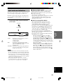
■ Connecting the AC power cord
Plug in this unit to a wall outlet.
■ AC OUTLETS (SWITCHED)
U.S.A., Canada, China, Europe, Singapore and
General models .............................................. 2 OUTLETS
U.K. and Australia model ................................ 1 OUTLET
Use these outlets to connect the power cords from your
components to this unit. The power to the AC OUTLETS
is controlled by this unit’s STANDBY/ON (or SYSTEM
POWER and STANDBY). These outlets will supply
power to any source component connected to this unit
whenever this unit is turned on. The maximum power
(total power consumption of components) that can be
connected to the AC OUTLETS varies depending on the
area which it was purchasing.
China and General models......................................... 50 W
Other models ......................................................... 100 W
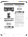
■ VOLTAGE SELECTOR
(China and General models only)
The VOLTAGE SELECTOR on the rear panel of this unit
must be set for your local main voltage BEFORE
plugging into the AC main supply. Voltages are 110/120/
220/240 V AC, 50/60 Hz.
VOLTAGE SELECTOR
Turning on the power
When all connections are complete, turn on the power of
this unit.
1 Press STANDBY/ON (SYSTEM POWER on
the remote control) to turn on the power of
this unit.
The level of the main volume, and then the current
DSP program name appear on the front panel
display.
STANDBY
/ON
POWER
SYSTEM
or
Remote control
Front panel
(General model)
REAR
CENTER
AC OUTLETS
SWITCHED
MAIN
CENTER
REAR CENTER
REAR
A OR B :
A+B :
:
:
:
4ΩMIN.
8ΩMIN.
6ΩMIN.
6ΩMIN.
6ΩMIN.
/SPEAKER
/SPEAKER
/SPEAKER
/SPEAKER
/SPEAKER
IMPEDANCE SELECTOR
SET BEFORE POWER ON
L
MAIN
CENTER
REAR CENTER
REAR
A OR B :
A+B :
:
:
:
8ΩMIN.
16ΩMIN.
8ΩMIN.
8ΩMIN.
8ΩMIN.
/SPEAKER
/SPEAKER
/SPEAKER
/SPEAKER
/SPEAKER
VOLTAGE
SELECTOR
INPUT
AUTO/MANUAL MONO
MAN`L/AUTO FM
TUNING MODE MEMORY
EDIT
PRESET/TUNING FM/AM
OPTICALRAUDIOLVIDEOS VIDEO
EFFECT
PRESET/TUNING
A/B/C/D/E
PROGRAMSTEREOSPEAKERS
BA
6CH INPUTINPUT MODE
SILENT
PHONES
TREBLE
VOLUME
BASS
VIDEO AUX
STANDBY
/ON
SET MENU
NEXT
1
TRANSMIT
RE
-
NAME
CLEAR
CODE SET
SYSTEM
POWER
STANDBY
6CH INPUT
SLEEP
A
PHONO
V
-
AUX
D
-
TV/CBL VCR 1 VCR2/DVR DVD
TUNER
MD
/
CD-R
CD
CB
SELECT
POWER
TV
AMP
POWER
AV
1
CONNECTIONS
0103RX-V740_09-19_EN-GB.p65 03.2.12, 4:23 PM18
Pagina se încarcă...
Pagina se încarcă...
Pagina se încarcă...
Pagina se încarcă...
Pagina se încarcă...
Pagina se încarcă...
Pagina se încarcă...
Pagina se încarcă...
Pagina se încarcă...
Pagina se încarcă...
Pagina se încarcă...
Pagina se încarcă...
Pagina se încarcă...
Pagina se încarcă...
Pagina se încarcă...
Pagina se încarcă...
Pagina se încarcă...
Pagina se încarcă...
Pagina se încarcă...
Pagina se încarcă...
Pagina se încarcă...
Pagina se încarcă...
Pagina se încarcă...
Pagina se încarcă...
Pagina se încarcă...
Pagina se încarcă...
Pagina se încarcă...
Pagina se încarcă...
Pagina se încarcă...
Pagina se încarcă...
Pagina se încarcă...
Pagina se încarcă...
Pagina se încarcă...
Pagina se încarcă...
Pagina se încarcă...
Pagina se încarcă...
Pagina se încarcă...
Pagina se încarcă...
Pagina se încarcă...
Pagina se încarcă...
Pagina se încarcă...
Pagina se încarcă...
Pagina se încarcă...
Pagina se încarcă...
Pagina se încarcă...
Pagina se încarcă...
Pagina se încarcă...
Pagina se încarcă...
-
 1
1
-
 2
2
-
 3
3
-
 4
4
-
 5
5
-
 6
6
-
 7
7
-
 8
8
-
 9
9
-
 10
10
-
 11
11
-
 12
12
-
 13
13
-
 14
14
-
 15
15
-
 16
16
-
 17
17
-
 18
18
-
 19
19
-
 20
20
-
 21
21
-
 22
22
-
 23
23
-
 24
24
-
 25
25
-
 26
26
-
 27
27
-
 28
28
-
 29
29
-
 30
30
-
 31
31
-
 32
32
-
 33
33
-
 34
34
-
 35
35
-
 36
36
-
 37
37
-
 38
38
-
 39
39
-
 40
40
-
 41
41
-
 42
42
-
 43
43
-
 44
44
-
 45
45
-
 46
46
-
 47
47
-
 48
48
-
 49
49
-
 50
50
-
 51
51
-
 52
52
-
 53
53
-
 54
54
-
 55
55
-
 56
56
-
 57
57
-
 58
58
-
 59
59
-
 60
60
-
 61
61
-
 62
62
-
 63
63
-
 64
64
-
 65
65
-
 66
66
-
 67
67
-
 68
68


Yamaha RX-V740RDS Manualul proprietarului
- Categorie
- Receptoare AV
- Tip
- Manualul proprietarului
în alte limbi
- Türkçe: Yamaha RX-V740RDS El kitabı
- français: Yamaha RX-V740RDS Le manuel du propriétaire
- English: Yamaha RX-V740RDS Owner's manual
- Deutsch: Yamaha RX-V740RDS Bedienungsanleitung
- italiano: Yamaha RX-V740RDS Manuale del proprietario
- svenska: Yamaha RX-V740RDS Bruksanvisning
- dansk: Yamaha RX-V740RDS Brugervejledning
- Nederlands: Yamaha RX-V740RDS de handleiding
Lucrări înrudite
-
Yamaha RX-V3000RDS Manual de utilizare
-
-
Yamaha RX-V596RDS Manualul proprietarului
-
-
-
-
-
-
-