Yamaha A-S1000 Manualul proprietarului
- Categorie
- Difuzoare
- Tip
- Manualul proprietarului
Acest manual este potrivit și pentru

BLACK
DIC 2181s*
© 2008 All rights reserved.
Printed in Malaysia WN63070
YAMAHA ELECTRONICS CORPORATION, USA 6660 ORANGETHORPE AVE., BUENA PARK, CALIF. 90620, U.S.A.
YAMAHA CANADA MUSIC LTD. 135 MILNER AVE., SCARBOROUGH, ONTARIO M1S 3R1, CANADA
YAMAHA ELECTRONIK EUROPA G.m.b.H. SIEMENSSTR. 22-34, 25462 RELLINGEN BEI HAMBURG, GERMANY
YAMAHA ELECTRONIQUE FRANCE S.A. RUE AMBROISE CROIZAT BP70 CROISSY-BEAUBOURG 77312 MARNE-LA-VALLEE CEDEX02, FRANCE
YAMAHA ELECTRONICS (UK) LTD. YAMAHA HOUSE, 200 RICKMANSWORTH ROAD WATFORD, HERTS WD18 7GQ, ENGLAND
YAMAHA SCANDINAVIA A.B. J A WETTERGRENS GATA 1, BOX 30053, 400 43 VÄSTRA FRÖLUNDA, SWEDEN
YAMAHA MUSIC AUSTRALIA PTY. LTD. LEVEL 1, 99 QUEENSBRIDGE STREET, SOUTHBANK, VIC 3006, AUSTRALIA
G
Stereo Amplifier
Amplificateur Stéréo
OWNER’S MANUAL
MODE D’EMPLOI
BEDIENUNGSANLEITUNG
BRUKSANVISNING
MANUALE DI ISTRUZIONI
MANUAL DE INSTRUCCIONES
GEBRUIKSAANWIJZING
ИНСТРУКЦИЯ ПО ЭКСПЛУАЦИИ

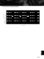
HiFi Began with Yamaha
Yamaha’s involvement with and passion for music goes back
more than a century, to when we built our first reed organ in
1887. Now we are the world’s leading producer of pianos and
other musical instruments, and are involved with music in many
other ways as well. We manufacture professional recording
equipment, we design concert halls and we assist artists at
concerts with set up and sound tuning.
This knowledge and experience benefits our production of
audio components in many ways. We introduced our first HiFi
(High Fidelity) turntable in 1955. Thereafter we were one of the first
to offer mass-produced, high quality audio equipment,
and introduced many legendary stereo components.
We hope you enjoy the genuine HiFi experience of
Yamaha Natural Sound.

CA-1000NS-20
NS-1000M
NS-10M
GT-2000
C-2
NS-690
B-1
B-6
GT-CD1AX-2000
Soavo-2Soavo-1
PX-1
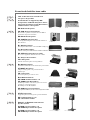
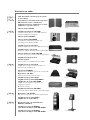
Excellence in Audio Achievement
1922: We introduced a high-quality hand-
wound phonograph.
Since 1955, we have released many HiFi
components, including turntables, tuners,
integrated amplifiers, control amplifiers,
power amplifiers and speakers.
NS-20 Monitor Speaker
CA-1000 Integrated Amplifier
Featuring A-Class operation, the CA-1000 set
the standard for integrated amplifiers.
NS-690 Monitor Speaker
NS-1000M Monitor Speaker
A truly legendary speaker still revered by HiFi enthusiasts
B-1 Power Amplifier
An innovative power amp that used FETs in all stages
C-2 Control Amplifier
Received top prize at the Milan International Music
and HiFi Show.
NS-10M Studio Monitor Speaker
Became of the most popular studio monitors in the world.
A-1 Integrated Amplifier
PX-1 Turntable
Yamaha’s first linear tracking turntable
B-6 Power Amplifier
Pyramid-shaped power amplifier with X power supply and
X amplifier
GT-2000/L Turntable
Ultra-precise heavyweight player embodying GT concept
CD-1 CD Player
First CD Player introduced in 1983
B-2x Power Amplifier
MX-10000 Power Amplifier and
CX-10000 Control Amplifier
Amplifier that redefined the capabilities of separate
components
100th anniversary model
AX-2000 Integrated Amplifier
High S/N ratio (128 dB), digital direct function equipped
GT-CD1 CD Player
Top-loading type player with integrated separate structure
MX-1 Power Amplifier and CX-1 Control
Amplifier
Soavo-1 and Soavo-2 Natural Sound
Speaker Systems
A-S2000 Stereo Amplifier and
CD-S2000 Super Audio CD Player
A-S1000 Stereo Amplifier and
CD-S1000 Super Audio CD Player

4 En
◆ Floating balanced circuit design
The perfectly symmetrical, fully new floating balanced power amplifier maximizes the performance of the analog
amplifier.
◆ Parallel volume and tone control
◆ Four independent high capacity power supplies
◆ Horizontally symmetrical structure
◆ Phono amplifier with fully discrete structure
◆ Newly developed heavyweight feet to suppress vibrations
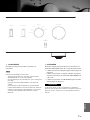
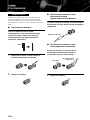
■ Supplied accessories
Please check that you have received all of the following parts.
• Remote control
• Batteries (AA, R6, UM-3) (×2)
• Power cable
• Safety brochure
■ About this manual
• y indicates a tip for your operation.
• This manual is printed prior to production. Design and specifications are subject to change in part as a result of improvements, etc. In
case of differences between the manual and the product, the product has priority.
• The color of images in this manual may vary from the original.
• Read the “Safety brochure” before using this unit.
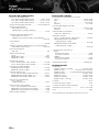
Contents
Controls and functions.......................................................................................................................................... 6
Connections.......................................................................................................................................................... 14
Specifications ....................................................................................................................................................... 20
Troubleshooting................................................................................................................................................... 24

5 En
Controls and functions
In this chapter, you will learn the controls and functions of A-S1000.

6 En
Controls and functions
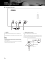
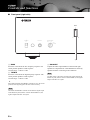
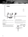
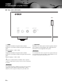
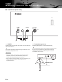
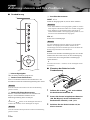
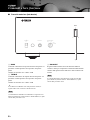
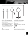
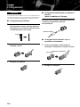
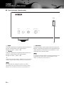
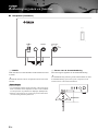
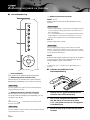
■ Front panel (left side)
1 POWER
Press upward or downward to turn on or off this unit.
y
The POWER indicator above lights up when this unit is turned
on.
• If the POWER indicator flashes when you turn on this unit,
disconnect the power cable and refer to the troubleshooting
section (page 24).
• When you turn on this unit, there will be a few second delay
before this unit can reproduce sound.
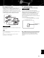
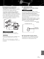
2 Remote control sensor
Receives signals from the remote control.
y
The remote control transmits a directional infrared beam. Be sure
to aim the remote control directly at the remote control sensor on
the front panel of this unit during operation.
SPEAKERSPHONESPOWER
OFF
ON
A
B
A+B
BI-WIRING
OFF
BASS
+
-
4132
Notes
30 30
Within 6 m (20 ft)

7 En
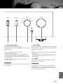
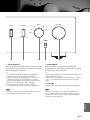
3 PHONES jack
Outputs audio for private listening with headphones.
When headphones are plugged in:
– Both speaker sets connected to the SPEAKERS L/R CH A
and B terminals are turned off.
– No signals are output at the PRE OUT jacks, while signals are
output at the REC jacks.
– You cannot select MAIN DIRECT as the input source.
– If headphones are plugged into the PHONES jack while
MAIN DIRECT is selected as the input source, no audio is
output at the PHONES jack. Use the headphones jack of the
preamplifier connected to the MAIN IN jacks.
4 SPEAKERS
Turns on or off the speaker set connected to the
SPEAKERS L/R CH A and/or B terminals on the rear
panel.
• Switch to the OFF position to turn off both speaker
sets.
• Switch to the A or B position to turn on the speaker set
connected to the SPEAKERS L/R CH A or B
terminals.
• Switch to the A+B BI-WIRING position to turn on
both speaker sets.
If you use two sets (A and B), the impedance of each speaker
must be 8 Ω or higher. When only using one set of speakers (A or
B), use speakers with an impedance of 4 Ω or higher.
BALANCE
VOLUMEINPUT
TREBLE
MAIN DIRECT
LINE 2
LINE 1
CD
TUNER
PHONO
AUDIO MUTE
RL+
-
Note
Caution
English

8 En
Controls and functions
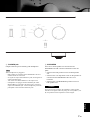
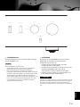
■ Front panel (right side)
5 BASS
Increases or decreases the low frequency response. The
center position produces a flat response.
Control range: –9 dB to +9 dB
6 TREBLE
Increases or decreases the high frequency response. The
center position produces a flat response.
Control range: –9 dB to +9 dB
y
When both the BASS and TREBLE controls are set to the center
position, audio signal bypasses the tone control circuitry.
The BASS and TREBLE controls do not affect the signals input
at the MAIN IN jacks (INPUT selector: MAIN DIRECT) and
signals output at the REC OUT jacks.
7 BALANCE
Adjusts the audio output balance of the left and right
speakers to compensate for sound imbalances caused by
speaker locations or listening room conditions.
The BALANCE control does not affect the signals input at the
MAIN IN jacks (INPUT selector: MAIN DIRECT) and signals
output at the REC OUT jacks.
SPEAKERSPHONESPOWER
OFF
ON
A
B
A+B
BI-WIRING
OFF
BASS
+
-
5
Note
Note

9 En
8 INPUT selector
Selects the input source you want to listen to.
The audio signals of the selected input source are also
output at the REC jacks.
y
• The input source names correspond to the names of the
connection jacks on the rear panel.
• Switch to the MAIN DIRECT position to select the component
connected to the MAIN IN jacks. When MAIN DIRECT is
selected as the input source, no signals are output at the PRE
OUT, REC, and PHONES jacks.
• The input setting is retained for about 1 week after the power is
turned off.
The audio signals are not output at the REC jacks while LINE2 is
selected as the input source.
9 AUDIO MUTE
Press downward to reduce the current volume level by
approximately 20 dB. Press again to restore the audio
output to the previous volume level.
y
• The AUDIO MUTE indicator lights up while the mute function
is on.
• You can also rotate VOLUME on the front panel or press
VOL +/– on the remote control to resume the audio output.
0 VOLUME
Controls the volume level. This does not affect the REC
level.
The VOLUME control does not affect when you select MAIN
DIRECT as the input source. Adjust the volume level using the
volume control on the preamplifier connected to the MAIN IN
jacks.
BALANCE
VOLUMEINPUT
TREBLE
MAIN DIRECT
LINE 2
LINE 1
CD
TUNER
PHONO
AUDIO MUTE
RL+
-
09876
Note Note
English

10 En
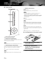
Controls and functions
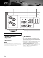
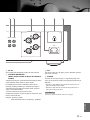
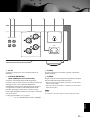
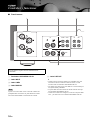
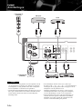
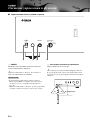
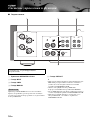
■ Rear panel
1 SPEAKERS L/R CH terminals
2 INPUT jacks
3 LINE2 jacks
4 MAIN IN jacks
Adjust the volume level using the volume control on the
preamplifier connected to the MAIN IN jacks when you select
MAIN DIRECT as the input source.
5 PRE OUT jacks
y
• When you connect audio pin plugs to the PRE OUT jacks to
drive the speakers using an external amplifier, it is not
necessary to use the SPEAKERS L/R CH terminals.
• The signal output at the PRE OUT jacks are affected by the
BASS and TREBLE settings.
• The PRE OUT jacks output the same channel signal as the
SPEAKERS L/R CH terminals.
• When you use a subwoofer, connect it to the PRE OUT jacks
and speakers to the SPEAKERS L/R CH terminals.
LINE2
RECPBLINE 1TUNER
GND
PHONO
CD
INPUT
SPEAKERS R CH
A
B
LR
MCMM
L
R
1 23
9
See page 14 for connection information.
Note

11 En
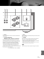
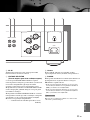
6 AC IN
Use this inlet to plug in the supplied power cable.
7 VOLTAGE SELECTOR
(Asia and General models only)
The VOLTAGE SELECTOR on the rear panel of this unit
must be set for your local main voltage BEFORE plugging
the power cable into the AC wall outlet. Improper setting
of the VOLTAGE SELECTOR may cause damage to this
unit and create a potential fire hazard.
Rotate the VOLTAGE SELECTOR clockwise or
counterclockwise to the correct position using a straight
slot screwdriver.
Voltages are as follows:
............................ AC 110/120/220/230–240 V, 50/60 Hz
8 Foot
If this unit is unstable, you can adjust the foot height by
rotating it.
9 PHONO
Selects the type of magnetic cartridge of the turntable
connected to the PHONO jacks on the rear panel.
• Set to the MM position when the connected turntable has a
moving magnet (MM) cartridge.
• Set to the MC position when the connected turntable has a
moving coil (MC) cartridge.
When you replace the cartridge, be sure to turn off this unit.
AC IN
SPEAKERS L CH
A
B
VOLTAGE SELECTOR
230-
240V
PRE OUTMAIN IN
5 1 7864
Note
English

12 En
Controls and functions
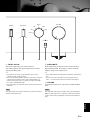
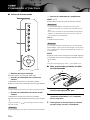
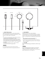
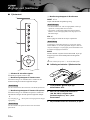
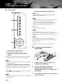
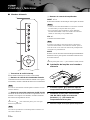
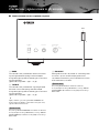
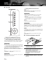
■ Remote control
1 Infrared signal transmitter
Outputs infrared control signals.
2 Yamaha tuner control buttons
Control functions of Yamaha tuner. Refer to the owner’s
manual of your tuner for details.
Not all Yamaha tuners can be controlled by this remote control.
3 Yamaha CD player control buttons
Control various functions of Yamaha CD player. Refer to
the owner’s manual of your CD player for details.
y
Press once to pause and twice to stop playback.
Not all Yamaha CD players can be controlled by this remote
control.
4 Amplifier control buttons
INPUT /
Selects the input source you want to listen to.
• When MAIN DIRECT is selected as the input source, no
signals are output at the PRE OUT and REC jacks.
• If headphones are plugged into the PHONES jack while MAIN
DIRECT is selected as the input source, no audio is output at
the PHONES jack.
VOL +/–
Controls the volume level.
The VOLUME control does not affect when you select MAIN
DIRECT as the input source. Adjust the volume level using the
volume control on the preamplifier connected to the MAIN IN
jacks.
MUTE
Reduces the current volume level by approximately 20
dB. Press again to restore the audio output to the previous
volume level.
y
You can also press VOL +/– to resume the audio output.
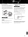
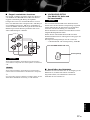
■ Installing batteries in the remote control
1 Press the part and slide the battery
compartment cover off.
2 Insert the two supplied batteries
(AA, R6, UM-3) according to the polarity
markings (+ and –) on the inside of the
battery compartment.
3 Slide the cover back until it snaps into place.
Note
Note
A/B/C/D/E
PRESET
INPUTINPUT
VOL
MUTE
VOL
1
2
3
4
Notes
Note
2
1
3

Connections
In this section, you will make connections between A-S1000, speakers,
and source components.

14 En
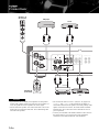
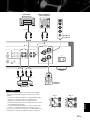
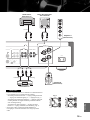
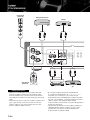
Connections
• If you use two sets (A and B), the impedance of each speaker
must be 8 Ω or higher. When only using one set of speakers (A
or B), use speakers with an impedance of 4 Ω or higher.
• Do not let the bare speaker wires touch each other or do not let
them touch any metal part of this unit. This could damage this
unit and/or the speakers.
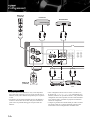
• All connections must be correct: L (left) to L, R (right) to R,
“+” to “+”, and “–” to “–”. If the connections are faulty, no
sound will be heard from the speakers, and if the polarity of the
speaker connections is incorrect, the sound will be unnatural
and lack bass. Also, refer to the owner’s manual for each of
your components.
• Connect your turntable to the GND terminal to reduce noise in
the signal. However, you may hear less noise without the
connection to the GND terminal for some turntables.
Caution
AC IN
LINE2
RECPBLINE 1TUNER
GND
PHONO
CD
INPUT
SPEAKERS R CH
A
B
LR
MCMM
L
R
PRE OUTMAIN IN
+
-
+
-
CD player
Ground
Speakers A
(R channel)
Speakers B
(R channel)
Tuner
Turntable
DVD player,
etc.

15 En
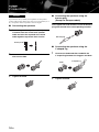
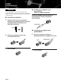
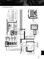
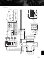
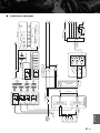
• Because the power amplifier of A-S1000 is of the floating
balanced type, the following types of connections are not
possible:
– Connecting with the left channel “–” terminal and the right
channel “–” terminal as well as “+” terminals (Fig. 1).
– Deliberately connecting with the left/right channel “–”
terminals and metal part on the rear panel of this unit, as well
as accidentally touching them.
– Connecting with the left channel “–” terminal and the right
channel “–” terminal inverted (cross connection, Fig. 2).
• Do not connect your active subwoofer to the SPEAKERS L/R
CH terminal. Connect it to the PRE OUT jacks of this unit.
Caution
AC IN
SPEAKERS L CH
LINE2
RECPBLINE 1TUNER
GND
N
O
D
INPUT
L
A
B
MCMM
L
R
PRE OUTMAIN IN
+–
+
-
CD recorder,
tape deck, etc.
Speakers A
(L channel)
Speakers B
(L channel)
External amplifier or
active subwoofer
Preamplifier,
AV receiver, etc.
Pre-out
Output Input
+
–
+
–
L
R
+
–
+
–
L
R
+
–
+
–
L
R
+
–
+
–
L
R
Fig. 1 Fig. 2
English

16 En
Connections
If you use two sets (A and B), the impedance of each speaker
must be 8 Ω or higher. When only using one set of speakers (A or
B), use speakers with an impedance of 4 Ω or higher.
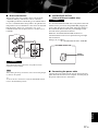
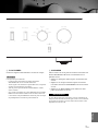
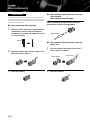
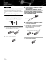
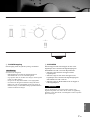
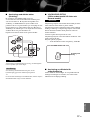
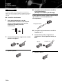
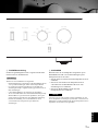
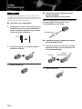
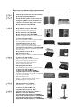
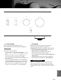
■ Connecting the speakers
1 Remove approximately 10 mm (0.4 in) of
insulation from the end of each speaker
cable and twist the exposed wires of the
cable together to prevent short circuits.
2 Unscrew the knob and then insert the bare
wire into the hole.
3 Tighten the knob.
■ Connecting the speakers using the
banana plug
(Except for Europe models)
First, tighten the knob and then insert the banana
plug into the end of the corresponding terminal.
■ Connecting the speakers using the
Y-shaped lug
1 Unscrew the knob and then sandwich the
Y-shaped lug between the ring part and base.
2 Tighten the knob.
Caution
10 mm (0.4 in)
Banana plug
Y-shaped lug
Slide

17 En
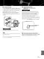
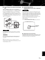
■ Bi-wire connection
The bi-wire connection separates the woofer from the
combined midrange and tweeter section. A bi-wire
compatible speaker has four binding post terminals. These
two sets of terminals allow the speaker to be split into two
independent sections. With these connections, the mid and
high frequency drivers are connected to one set of
terminals and the low frequency driver to another set of
terminals.
When making bi-wiring connections, use speakers with an
impedance of 4 Ω or higher.
When making bi-wiring connections, remove the shorting bridges
or cables on the speaker.
y
To use the bi-wire connections, switch the SPEAKERS selector
to the A+B BI-WIRING position.
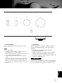
■ VOLTAGE SELECTOR
(Asia and General models only)
The VOLTAGE SELECTOR on the rear panel of this unit
must be set for your local voltage BEFORE plugging the
power cable into the AC wall outlet. Improper setting of
the VOLTAGE SELECTOR may cause damage to this
unit and create a potential fire hazard.
Rotate the VOLTAGE SELECTOR clockwise or
counterclockwise to the correct position using a straight
slot screwdriver.
Voltages are as follows:
........................ AC 110/120/220/230–240 V, 50/60 Hz
■ Connecting the power cable
Connect the power cable into the AC IN inlet on the rear
panel when all connections are complete, and then plug in
the power cable to the AC wall outlet.
Caution
Note
SPEAKERS L CH
A
B
Caution
230-
240V
VOLTAGE SELECTOR
Voltage
indication
English

18 En
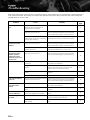
Connections
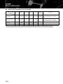
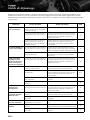
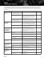
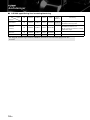
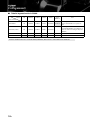
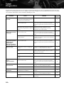
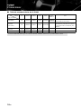
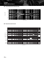
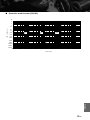
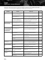
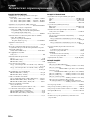
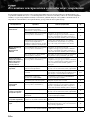
■ A-S1000 input/output table
CD PHONO TUNER LINE1 LINE2
MAIN
DIRECT
Note
SPEAKERS CD PHONO TUNER LINE1 LINE2 PB MAIN IN
No signal is output while the SPEAKERS
selector is switched to the OFF position.
PHONES
(Headphones)
CD PHONO TUNER LINE1 LINE2 PB –
No signal is output at the SPEAKERS
terminals and PRE OUT jacks while
headphones are connected to the
PHONES jack.
PRE OUT CD PHONO TUNER LINE1 LINE2 PB –
LINE2 REC CD PHONO TUNER LINE1 – –
The shaded area indicates that the BASS, TREBLE, BALANCE, and VOLUME controls are ineffective.
INPUT
selector
Output jacks

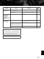
Specifications
In this section, you will find technical specifications for A-S1000.

20 En
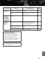
Specifications
POWER SECTION
• Minimum RMS Output Power
(8 Ω , 20 Hz to 20 kHz, 0.02% THD) ...................... 90 W + 90 W
(6 Ω , 20 Hz to 20 kHz, 0.02% THD) .................. 105 W + 105 W
(4 Ω , 20 Hz to 20 kHz, 0.02% THD) .................. 140 W + 140 W
• Dynamic Power (IHF) (8/6/4/2 Ω) ................... 105/135/190/220 W
• Maximum Output Power
(1 kHz, 0.7% THD, 4 Ω) [U.K. and Europe models only]
.......................................................................................... 160 W
• Maximum Useful Output Power (JEITA)
(1 kHz, 10% THD, 8/4 Ω)
[Asia, General, China and Korea models only] ....... 115/190 W
• Dynamic Headroom
8 Ω ..................................................................................... 0.67 dB
• IEC Output Power [U.K. and Europe models only]
(1 kHz, 0.02% THD, 8/4 Ω)............................................ 90/145 W
• Damping Factor
1 kHz, 8 Ω ................................................................................ 160
• Maximum Input Signal
CD, etc. ................................................................................. 2.8 V
PHONO MM (1 kHz) ........................................................ 120 mV
PHONO MC (1 kHz) ............................................................ 7 mV
• Frequency Response
CD, etc. (Flat Position, 5 Hz to 100 kHz) ...................... +0/−3 dB
CD, etc. (Flat Position, 20 Hz to 20 kHz) ................... +0/−0.3 dB
• RIAA Equalization Deviation
PHONO MM (20 Hz to 20 kHz) ...................................... ±0.5 dB
PHONO MC (20 Hz to 20 kHz) ....................................... ±0.5 dB
• Total Harmonic Distortion
CD, etc. to SP OUT
(20 Hz to 20 kHz, 90 W/8 Ω) ........................................... 0.015%
PHONO MM to REC
(20 Hz to 20 kHz, 2 V) ..................................................... 0.005%
PHONO MC to REC
(20 Hz to 20 kHz, 2 V) ....................................................... 0.05%
• Intermodulation Distortion
CD, etc. to SP OUT
(Rated output, 8 Ω) ............................................................0.02%
• Signal to Noise Ratio (IHF-A Network)
CD, etc. (150 mV, Input shorted) ..........................................98 dB
PHONO MM (5 mV, Input shorted) .....................................93 dB
PHONO MC (500 µV, Input shorted) ..................................85 dB
• Residual Noise (IHF-A Network) .......................................... 73 µV
CONTROL SECTION
• Input Sensitivity/Input Impedance
CD, etc. .................................................................. 150 mV/47 kΩ
MM ......................................................................... 2.5 mV/47 kΩ
MC ........................................................................... 100 µV/50 Ω
MAIN IN ...................................................................... 1 V/47 kΩ
• Output Level/Output Impedance
REC OUT ............................................................. 150 mV/1.5 kΩ
PRE OUT ..................................................................... 1 V/1.5 kΩ
• Headphone Rated Output
1 kHz, 32 Ω , 0.2% THD ................................................... 23 mW
• Channel Separation
CD, etc. (5.1 kΩ Terminated, 1 kHz/10 kHz) ................. 74/54 dB
PHONO MM (Input shorted, 1 kHz/10 kHz, Vol.:−30 dB)
....................................................................................... 90/77 dB
PHONO MC (Input shorted, 1 kHz/10 kHz, Vol.:−30 dB)
....................................................................................... 66/65 dB
• Tone Control Characteristics
BASS
Boost/Cut (50 Hz) ............................................................. ±9 dB
Turnover Frequency ........................................................ 350 Hz
TREBLE
Boost/Cut (20 kHz) ........................................................... ±9 dB
Turnover Frequency ....................................................... 3.5 kHz
• Audio muting......................................................... –20 dB (approx.)
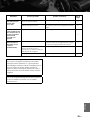
GENERAL
• Power Supply
[U.S.A. and Canada models] ............................. AC 120 V, 60 Hz
[Asia model] .................................. AC 220/230–240 V, 50/60 Hz
[General model] ............... AC 110/120/220/230–240 V, 50/60 Hz
[China model] .................................................... AC 220 V, 50 Hz
[Korea model] .................................................... AC 220 V, 60 Hz
[Australia model] ............................................... AC 240 V, 50 Hz
[U.K. and Europe models] ................................. AC 230 V, 50 Hz
• Power consumption ................................................................ 350 W
• Idling power consumption......................................................... 80 W
• Off-state power consumption ......................................................0 W
• Dimensions (W x H x D) ................................. 435 x 137 x 465 mm
(17-1/8” x 5-3/8” x 18-5/16”)
• Weight ............................................................... 22 kg (48 lbs. 8 oz.)
* Specifications are subject to change without notice.
Pagina se încarcă ...
Pagina se încarcă ...
Pagina se încarcă ...
Pagina se încarcă ...
Pagina se încarcă ...
Pagina se încarcă ...
Pagina se încarcă ...
Pagina se încarcă ...
Pagina se încarcă ...
Pagina se încarcă ...
Pagina se încarcă ...
Pagina se încarcă ...
Pagina se încarcă ...
Pagina se încarcă ...
Pagina se încarcă ...
Pagina se încarcă ...
Pagina se încarcă ...
Pagina se încarcă ...
Pagina se încarcă ...
Pagina se încarcă ...
Pagina se încarcă ...
Pagina se încarcă ...
Pagina se încarcă ...
Pagina se încarcă ...
Pagina se încarcă ...
Pagina se încarcă ...
Pagina se încarcă ...
Pagina se încarcă ...
Pagina se încarcă ...
Pagina se încarcă ...
Pagina se încarcă ...
Pagina se încarcă ...
Pagina se încarcă ...
Pagina se încarcă ...
Pagina se încarcă ...
Pagina se încarcă ...
Pagina se încarcă ...
Pagina se încarcă ...
Pagina se încarcă ...
Pagina se încarcă ...
Pagina se încarcă ...
Pagina se încarcă ...
Pagina se încarcă ...
Pagina se încarcă ...
Pagina se încarcă ...
Pagina se încarcă ...
Pagina se încarcă ...
Pagina se încarcă ...
Pagina se încarcă ...
Pagina se încarcă ...
Pagina se încarcă ...
Pagina se încarcă ...
Pagina se încarcă ...
Pagina se încarcă ...
Pagina se încarcă ...
Pagina se încarcă ...
Pagina se încarcă ...
Pagina se încarcă ...
Pagina se încarcă ...
Pagina se încarcă ...
Pagina se încarcă ...
Pagina se încarcă ...
Pagina se încarcă ...
Pagina se încarcă ...
Pagina se încarcă ...
Pagina se încarcă ...
Pagina se încarcă ...
Pagina se încarcă ...
Pagina se încarcă ...
Pagina se încarcă ...
Pagina se încarcă ...
Pagina se încarcă ...
Pagina se încarcă ...
Pagina se încarcă ...
Pagina se încarcă ...
Pagina se încarcă ...
Pagina se încarcă ...
Pagina se încarcă ...
Pagina se încarcă ...
Pagina se încarcă ...
Pagina se încarcă ...
Pagina se încarcă ...
Pagina se încarcă ...
Pagina se încarcă ...
Pagina se încarcă ...
Pagina se încarcă ...
Pagina se încarcă ...
Pagina se încarcă ...
Pagina se încarcă ...
Pagina se încarcă ...
Pagina se încarcă ...
Pagina se încarcă ...
Pagina se încarcă ...
Pagina se încarcă ...
Pagina se încarcă ...
Pagina se încarcă ...
Pagina se încarcă ...
Pagina se încarcă ...
Pagina se încarcă ...
Pagina se încarcă ...
Pagina se încarcă ...
Pagina se încarcă ...
Pagina se încarcă ...
Pagina se încarcă ...
Pagina se încarcă ...
Pagina se încarcă ...
Pagina se încarcă ...
Pagina se încarcă ...
Pagina se încarcă ...
Pagina se încarcă ...
Pagina se încarcă ...
Pagina se încarcă ...
Pagina se încarcă ...
Pagina se încarcă ...
Pagina se încarcă ...
Pagina se încarcă ...
Pagina se încarcă ...
Pagina se încarcă ...
Pagina se încarcă ...
Pagina se încarcă ...
Pagina se încarcă ...
Pagina se încarcă ...
Pagina se încarcă ...
Pagina se încarcă ...
Pagina se încarcă ...
Pagina se încarcă ...
Pagina se încarcă ...
Pagina se încarcă ...
Pagina se încarcă ...
Pagina se încarcă ...
Pagina se încarcă ...
Pagina se încarcă ...
Pagina se încarcă ...
Pagina se încarcă ...
Pagina se încarcă ...
Pagina se încarcă ...
Pagina se încarcă ...
Pagina se încarcă ...
Pagina se încarcă ...
Pagina se încarcă ...
Pagina se încarcă ...
Pagina se încarcă ...
Pagina se încarcă ...
Pagina se încarcă ...
Pagina se încarcă ...
Pagina se încarcă ...
Pagina se încarcă ...
Pagina se încarcă ...
Pagina se încarcă ...
Pagina se încarcă ...
Pagina se încarcă ...
Pagina se încarcă ...
Pagina se încarcă ...
Pagina se încarcă ...
Pagina se încarcă ...
Pagina se încarcă ...
Pagina se încarcă ...
Pagina se încarcă ...
Pagina se încarcă ...
Pagina se încarcă ...
Pagina se încarcă ...
Pagina se încarcă ...
Pagina se încarcă ...
Pagina se încarcă ...
Pagina se încarcă ...
Pagina se încarcă ...
Pagina se încarcă ...
Pagina se încarcă ...
Pagina se încarcă ...
Pagina se încarcă ...
Pagina se încarcă ...
Pagina se încarcă ...
Pagina se încarcă ...
Pagina se încarcă ...
Pagina se încarcă ...
Pagina se încarcă ...
Pagina se încarcă ...
Pagina se încarcă ...
Pagina se încarcă ...
Pagina se încarcă ...
Pagina se încarcă ...
Pagina se încarcă ...
Pagina se încarcă ...
Pagina se încarcă ...
Pagina se încarcă ...
Pagina se încarcă ...
Pagina se încarcă ...
Pagina se încarcă ...
Pagina se încarcă ...
Pagina se încarcă ...
Pagina se încarcă ...
Pagina se încarcă ...
-
 1
1
-
 2
2
-
 3
3
-
 4
4
-
 5
5
-
 6
6
-
 7
7
-
 8
8
-
 9
9
-
 10
10
-
 11
11
-
 12
12
-
 13
13
-
 14
14
-
 15
15
-
 16
16
-
 17
17
-
 18
18
-
 19
19
-
 20
20
-
 21
21
-
 22
22
-
 23
23
-
 24
24
-
 25
25
-
 26
26
-
 27
27
-
 28
28
-
 29
29
-
 30
30
-
 31
31
-
 32
32
-
 33
33
-
 34
34
-
 35
35
-
 36
36
-
 37
37
-
 38
38
-
 39
39
-
 40
40
-
 41
41
-
 42
42
-
 43
43
-
 44
44
-
 45
45
-
 46
46
-
 47
47
-
 48
48
-
 49
49
-
 50
50
-
 51
51
-
 52
52
-
 53
53
-
 54
54
-
 55
55
-
 56
56
-
 57
57
-
 58
58
-
 59
59
-
 60
60
-
 61
61
-
 62
62
-
 63
63
-
 64
64
-
 65
65
-
 66
66
-
 67
67
-
 68
68
-
 69
69
-
 70
70
-
 71
71
-
 72
72
-
 73
73
-
 74
74
-
 75
75
-
 76
76
-
 77
77
-
 78
78
-
 79
79
-
 80
80
-
 81
81
-
 82
82
-
 83
83
-
 84
84
-
 85
85
-
 86
86
-
 87
87
-
 88
88
-
 89
89
-
 90
90
-
 91
91
-
 92
92
-
 93
93
-
 94
94
-
 95
95
-
 96
96
-
 97
97
-
 98
98
-
 99
99
-
 100
100
-
 101
101
-
 102
102
-
 103
103
-
 104
104
-
 105
105
-
 106
106
-
 107
107
-
 108
108
-
 109
109
-
 110
110
-
 111
111
-
 112
112
-
 113
113
-
 114
114
-
 115
115
-
 116
116
-
 117
117
-
 118
118
-
 119
119
-
 120
120
-
 121
121
-
 122
122
-
 123
123
-
 124
124
-
 125
125
-
 126
126
-
 127
127
-
 128
128
-
 129
129
-
 130
130
-
 131
131
-
 132
132
-
 133
133
-
 134
134
-
 135
135
-
 136
136
-
 137
137
-
 138
138
-
 139
139
-
 140
140
-
 141
141
-
 142
142
-
 143
143
-
 144
144
-
 145
145
-
 146
146
-
 147
147
-
 148
148
-
 149
149
-
 150
150
-
 151
151
-
 152
152
-
 153
153
-
 154
154
-
 155
155
-
 156
156
-
 157
157
-
 158
158
-
 159
159
-
 160
160
-
 161
161
-
 162
162
-
 163
163
-
 164
164
-
 165
165
-
 166
166
-
 167
167
-
 168
168
-
 169
169
-
 170
170
-
 171
171
-
 172
172
-
 173
173
-
 174
174
-
 175
175
-
 176
176
-
 177
177
-
 178
178
-
 179
179
-
 180
180
-
 181
181
-
 182
182
-
 183
183
-
 184
184
-
 185
185
-
 186
186
-
 187
187
-
 188
188
-
 189
189
-
 190
190
-
 191
191
-
 192
192
-
 193
193
-
 194
194
-
 195
195
-
 196
196
-
 197
197
-
 198
198
-
 199
199
-
 200
200
-
 201
201
-
 202
202
-
 203
203
-
 204
204
-
 205
205
-
 206
206
-
 207
207
-
 208
208
-
 209
209
-
 210
210
-
 211
211
-
 212
212


Yamaha A-S1000 Manualul proprietarului
- Categorie
- Difuzoare
- Tip
- Manualul proprietarului
- Acest manual este potrivit și pentru
în alte limbi
- Türkçe: Yamaha A-S1000 El kitabı
- français: Yamaha A-S1000 Le manuel du propriétaire
- русский: Yamaha A-S1000 Инструкция по применению
- English: Yamaha A-S1000 Owner's manual
- suomi: Yamaha A-S1000 Omistajan opas
- Deutsch: Yamaha A-S1000 Bedienungsanleitung
- italiano: Yamaha A-S1000 Manuale del proprietario
- español: Yamaha A-S1000 El manual del propietario
- svenska: Yamaha A-S1000 Bruksanvisning
- dansk: Yamaha A-S1000 Brugervejledning
- Nederlands: Yamaha A-S1000 de handleiding
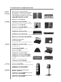
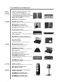
Lucrări conexe
-
Yamaha A-S2000 Manualul proprietarului
-
Yamaha DSP-A1092 Manualul proprietarului
-
Yamaha R-S500 Manualul proprietarului
-
-
-
Yamaha R-N500 Black Manual de utilizare
-
-
-
-