Makita DHR183 Manual de utilizare
- Categorie
- Unelte electrice
- Tip
- Manual de utilizare

DHR183
EN Cordless Rotary Hammer INSTRUCTION MANUAL 8
SL Brezžično vrtalno kladivo NAVODILA ZA UPORABO 18
SQ Çekiçi rrotullues me bateri MANUALI I PËRDORIMIT 28
BG Безжична ударна
бормашина РЪКОВОДСТВО ЗА
ЕКСПЛОАТАЦИЯ 39
HR Bežična udarna bušilica PRIRUČNIK S UPUTAMA 51
МК Безжична чекан-дупчалка УПАТСТВО ЗА УПОТРЕБА 61
SR Бежична ударна бушилица УПУТСТВО ЗА УПОТРЕБУ 72
RO Ciocan rotopercutor cu
acumulator MANUAL DE INSTRUCŢIUNI 83
UK Бездротовий перфоратор ІНСТРУКЦІЯ З
ЕКСПЛУАТАЦІЇ 94
RU Аккумуляторный
Перфоратор РУКОВОДСТВО ПО
ЭКСПЛУАТАЦИИ 106

2
1
2
3
Fig.1
1
2
Fig.2
1
Fig.3
1
Fig.4
1
AB
Fig.5
1
Fig.6
1
Fig.7
1
Fig.8

3
1
Fig.9
1
2
Fig.10
1
Fig.11
1
2
Fig.12
3
1 2
4
Fig.13
1
Fig.14
2
1
Fig.15

4
1
2
3
Fig.16
1
Fig.17
1
2
Fig.18
1
Fig.19
1
Fig.20
1
2
1
2
Fig.21
1
2
Fig.22

5
1
2
35
4
Fig.23
2
1
Fig.24
1
Fig.25
Fig.26
Fig.27
1
2
3
4
Fig.28

6
4
3
1
2
Fig.29
1
2
Fig.30
1
Fig.31
1
Fig.32
Fig.33
1
Fig.34
1
Fig.35
1
2
Fig.36

7
1
2
34
Fig.37
1
2
43
Fig.38
2
1
3
4
5
Fig.39
1
2
3
Fig.40
Fig.41
12
Fig.42
Fig.43
Fig.44

8ENGLISH
ENGLISH (Original instructions)
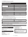
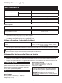
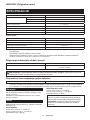
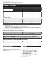
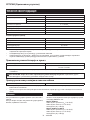
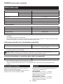
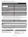
SPECIFICATIONS
Model: DHR183
Drilling capacities Concrete 18 mm
Steel 13 mm
Wood 24 mm
No load speed 0 - 1,100 min-1
Blows per minute 0 - 5,000 min-1
Overall length (with BL1860B) 288 mm
Rated voltage D.C. 18 V
Net weight 2.1 - 2.9 kg
Optional accessory
Model: DX16
Suction performance 0.24 l/min
Operating stroke Up to 105 mm
Suitable drill bit Up to 165 mm
Net weight 0.77 kg
• Duetoourcontinuingprogramofresearchanddevelopment,thespecicationshereinaresubjecttochange
without notice.
• Specicationsmaydierfromcountrytocountry.
• Theweightmaydierdependingontheattachment(s),includingthebatterycartridge.Thelightestandheavi-
est combinations, according to EPTA-Procedure 01/2014, are shown in the table.
Applicable battery cartridge and charger
Batterycartridge BL1815N / BL1820B / BL1830B / BL1840B / BL1850B / BL1860B
Charger DC18RC / DC18RD / DC18RE / DC18SD / DC18SE / DC18SF /
DC18SH / DC18WC
•
Someofthebatterycartridgesandchargerslistedabovemaynotbeavailabledependingonyourregionofresidence.
WARNING: Only use the battery cartridges and chargers listed above.Useofanyotherbatterycartridges
andchargersmaycauseinjuryand/orre.
Recommended cord connected power source
Portable power pack PDC01
• Thecordconnectedpowersource(s)listedabovemaynotbeavailabledependingonyourregionofresidence.
• Beforeusingthecordconnectedpowersource,readinstructionandcautionarymarkingsonthem.
Intended use
The tool is intended for hammer drilling and drilling in
brick, concrete and stone.
It is also suitable for drilling without impact in wood,
metal, ceramic and plastic.
Noise
ThetypicalA-weightednoiseleveldeterminedaccord-
ing to EN62841-2-6:
Model DHR183
Sound pressure level (LpA) : 90 dB (A)
Sound power level (LWA) : 101 dB (A)
Uncertainty(K):3dB(A)
Model DHR183 with DX16
Sound pressure level (LpA) : 90 dB(A)
Sound power level (LWA) : 101 dB (A)
Uncertainty(K):3dB(A)
NOTE: The declared noise emission value(s) has
been measured in accordance with a standard test
methodandmaybeusedforcomparingonetoolwith
another.
NOTE: The declared noise emission value(s)
mayalsobeusedinapreliminaryassessmentof
exposure.

9ENGLISH
WARNING: Wear ear protection.
WARNING: The noise emission during actual
use of the power tool can dier from the declared
value(s) depending on the ways in which the
tool is used especially what kind of workpiece is
processed.
WARNING: Be sure to identify safety mea-
sures to protect the operator that are based on an
estimation of exposure in the actual conditions of
use (taking account of all parts of the operating
cycle such as the times when the tool is switched
o and when it is running idle in addition to the
trigger time).
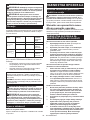
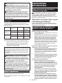
Vibration
The following table shows the vibration total value
(tri-axial vector sum) determined according to applica-
ble standard.
Work mode Vibration
emission
Uncertainty (K)
Applicable
standard /
Test condition
Hammer
drilling into
concrete
(ah, HD)
7.5 m/s21.5 m/s2EN62841-2-6
7.5 m/s21.5 m/s2
Recommended
practical
operation*
Hammer
drilling into
concrete with
DX16 (ah, HD)
7.6 m/s21.7 m/s2EN62841-2-6
7.7 m/s21.5 m/s2
Recommended
practical
operation*
* The test condition of recommended practical operation
meets EN 62841-2-6, except for the following points:
• Feed force is applied to the switch handle (main
handle)forworkingaccuracyandeciency.
• Thesidegrip/handle(auxiliaryhandle)isheldto
keep balance of the tool.
NOTE: The declared vibration total value(s) has been
measured in accordance with a standard test method
andmaybeusedforcomparingonetoolwithanother.
NOTE:Thedeclaredvibrationtotalvalue(s)mayalso
beusedinapreliminaryassessmentofexposure.
WARNING: The vibration emission during
actual use of the power tool can dier from the
declared value(s) depending on the ways in which
the tool is used especially what kind of workpiece
is processed.
WARNING: Be sure to identify safety mea-
sures to protect the operator that are based on an
estimation of exposure in the actual conditions of
use (taking account of all parts of the operating
cycle such as the times when the tool is switched
o and when it is running idle in addition to the
trigger time).
Declarations of Conformity
For European countries only
TheDeclarationsofconformityareincludedinAnnexA
to this instruction manual.
SAFETY WARNINGS
General power tool safety warnings
WARNING Read all safety warnings, instruc-
tions, illustrations and specications provided with
this power tool. Failure to follow all instructions listed
belowmayresultinelectricshock,reand/orserious
injury.
Save all warnings and instruc-
tions for future reference.
Theterm"powertool"inthewarningsreferstoyour
mains-operated(corded)powertoolorbattery-operated
(cordless) power tool.
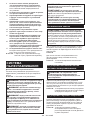
CORDLESS ROTARY HAMMER
SAFETY WARNINGS
Safety instructions for all operations
1. Wear ear protectors. Exposure to noise can
cause hearing loss.
2. Use auxiliary handle(s), if supplied with the
tool.Lossofcontrolcancausepersonalinjury.
3.
Hold the power tool by insulated gripping sur-
faces, when performing an operation where the
cutting accessory may contact hidden wiring.
Cuttingaccessorycontactinga"live"wiremay
make exposed metal parts of the power tool "live"
and could give the operator an electric shock.
Safety instructions when using long drill bits with
rotary hammers
1. Always start drilling at low speed and with the
bit tip in contact with the workpiece. At higher
speeds,thebitislikelytobendifallowedtorotate
freelywithoutcontactingtheworkpiece,resulting
inpersonalinjury.
2. Apply pressure only in direct line with the bit
and do not apply excessive pressure. Bits can
bend, causing breakage or loss of control, result-
inginpersonalinjury.
Additional safety warnings
1. Wear a hard hat (safety helmet), safety glasses
and/or face shield. Ordinary eye or sun glasses
are NOT safety glasses. It is also highly recom-
mended that you wear a dust mask and thickly
padded gloves.
2. Be sure the bit is secured in place before
operation.
3. Under normal operation, the tool is designed
to produce vibration. The screws can come
loose easily, causing a breakdown or accident.
Check tightness of screws carefully before
operation.
4. In cold weather or when the tool has not been
used for a long time, let the tool warm up for
a while by operating it under no load. This
will loosen up the lubrication. Without proper
warm-up, hammering operation is dicult.
5. Always be sure you have a rm footing. Be
sure no one is below when using the tool in
high locations.

10 ENGLISH
6. Hold the tool rmly with both hands.
7. Keep hands away from moving parts.
8. Do not leave the tool running. Operate the tool
only when hand-held.
9. Do not point the tool at any one in the area
when operating. The bit could y out and
injure someone seriously.
10.
Do not touch the bit, parts close to the bit, or
workpiece immediately after operation; they may
be extremely hot and could burn your skin.
11. Some material contains chemicals which may
be toxic. Take caution to prevent dust inhala-
tion and skin contact. Follow material supplier
safety data.
12. Always be sure that the tool is switched
o and the battery cartridge and the bit are
removed before handing the tool to other
person.
13. Before operation, make sure that there is no
buried object such as electric pipe, water pipe
or gas pipe in the working area. Otherwise, the
drillbit/chiselmaytouchthem,resultinganelectric
shock, electrical leakage or gas leak.
14. Do not operate the tool at no-load
unnecessarily.
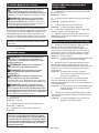
SAVE THESE INSTRUCTIONS.
WARNING: DO NOT let comfort or familiarity
with product (gained from repeated use) replace
strict adherence to safety rules for the subject
product. MISUSE or failure to follow the safety
rules stated in this instruction manual may cause
serious personal injury.
Important safety instructions for
battery cartridge
1. Before using battery cartridge, read all instruc-
tions and cautionary markings on (1) battery
charger, (2) battery, and (3) product using
battery.
2. Do not disassemble or tamper with the battery
cartridge.Itmayresultinare,excessiveheat,
or explosion.
3. If operating time has become excessively
shorter, stop operating immediately. It may
result in a risk of overheating, possible burns
and even an explosion.
4. If electrolyte gets into your eyes, rinse them
out with clear water and seek medical atten-
tion right away. It may result in loss of your
eyesight.
5. Do not short the battery cartridge:
(1) Do not touch the terminals with any con-
ductive material.
(2) Avoid storing battery cartridge in a con-
tainer with other metal objects such as
nails, coins, etc.
(3) Do not expose battery cartridge to water
or rain.
A battery short can cause a large current
ow, overheating, possible burns and even a
breakdown.
6. Do not store and use the tool and battery car-
tridge in locations where the temperature may
reach or exceed 50 °C (122 °F).
7. Do not incinerate the battery cartridge even if
it is severely damaged or is completely worn
out. The battery cartridge can explode in a re.
8. Do not nail, cut, crush, throw, drop the battery
cartridge, or hit against a hard object to the
battery cartridge.Suchconductmayresultina
re,excessiveheat,orexplosion.
9. Do not use a damaged battery.
10. The contained lithium-ion batteries are subject
to the Dangerous Goods Legislation require-
ments.
Forcommercialtransportse.g.bythirdparties,
forwarding agents, special requirement on pack-
aging and labeling must be observed.
For preparation of the item being shipped, consult-
ing an expert for hazardous material is required.
Pleasealsoobservepossiblymoredetailed
national regulations.
Tapeormaskoopencontactsandpackupthe
batteryinsuchamannerthatitcannotmove
around in the packaging.
11. When disposing the battery cartridge, remove
it from the tool and dispose of it in a safe
place. Follow your local regulations relating to
disposal of battery.
12. Use the batteries only with the products
specied by Makita. Installing the batteries to
non-compliantproductsmayresultinare,exces-
siveheat,explosion,orleakofelectrolyte.
13. If the tool is not used for a long period of time,
the battery must be removed from the tool.
14. During and after use, the battery cartridge may
take on heat which can cause burns or low
temperature burns. Pay attention to the han-
dling of hot battery cartridges.
15. Do not touch the terminal of the tool imme-
diately after use as it may get hot enough to
cause burns.
16. Do not allow chips, dust, or soil stuck into the
terminals, holes, and grooves of the battery
cartridge.Itmaycauseheating,catchingre,
burstandmalfunctionofthetoolorbatterycar-
tridge,resultinginburnsorpersonalinjury.
17. Unless the tool supports the use near
high-voltage electrical power lines, do not use
the battery cartridge near high-voltage electri-
cal power lines.Itmayresultinamalfunctionor
breakdownofthetoolorbatterycartridge.
18. Keep the battery away from children.
SAVE THESE INSTRUCTIONS.
CAUTION: Only use genuine Makita batteries.
Use of non-genuine Makita batteries, or batteries that
havebeenaltered,mayresultinthebatterybursting
causingres,personalinjuryanddamage.Itwill
alsovoidtheMakitawarrantyfortheMakitatooland
charger.

11 ENGLISH
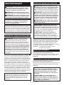
Tips for maintaining maximum
battery life
1. Charge the battery cartridge before completely
discharged. Always stop tool operation and
charge the battery cartridge when you notice
less tool power.
2. Never recharge a fully charged battery car-
tridge. Overcharging shortens the battery
service life.
3. Charge the battery cartridge with room tem-
perature at 10 °C - 40 °C (50 °F - 104 °F). Let
a hot battery cartridge cool down before
charging it.
4. When not using the battery cartridge, remove
it from the tool or the charger.
5. Charge the battery cartridge if you do not use
it for a long period (more than six months).
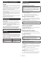
FUNCTIONAL
DESCRIPTION
CAUTION: Always be sure that the tool is
switched o and the battery cartridge is removed
before adjusting or checking function on the tool.
Installing or removing battery
cartridge
CAUTION: Always switch o the tool before
installing or removing of the battery cartridge.
CAUTION: Hold the tool and the battery car-
tridge rmly when installing or removing battery
cartridge.Failuretoholdthetoolandthebattery
cartridgermlymaycausethemtoslipoyourhands
andresultindamagetothetoolandbatterycartridge
andapersonalinjury.
Toinstallthebatterycartridge,alignthetongueonthe
batterycartridgewiththegrooveinthehousingandslip
itintoplace.Insertitallthewayuntilitlocksinplace
withalittleclick.Ifyoucanseetheredindicatoras
showninthegure,itisnotlockedcompletely.
Toremovethebatterycartridge,slideitfromthetool
while sliding the button on the front of the cartridge.
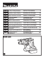
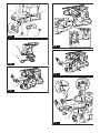
►Fig.1: 1. Red indicator 2. Button 3.Batterycartridge
CAUTION: Always install the battery cartridge
fully until the red indicator cannot be seen. If not,
itmayaccidentallyfalloutofthetool,causinginjuryto
youorsomeonearoundyou.
CAUTION: Do not install the battery cartridge
forcibly.Ifthecartridgedoesnotslideineasily,itis
notbeinginsertedcorrectly.
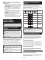
Indicating the remaining battery
capacity
Only for battery cartridges with the indicator
Pressthecheckbuttononthebatterycartridgetoindi-
catetheremainingbatterycapacity.Theindicatorlamps
light up for a few seconds.
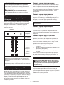
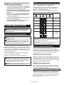
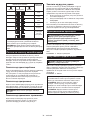
►Fig.2: 1. Indicator lamps 2. Check button
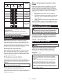
Indicator lamps Remaining
capacity
Lighted O Blinking
75% to 100%
50% to 75%
25% to 50%
0% to 25%
Charge the
battery.
Thebattery
mayhave
malfunctioned.
NOTE: Depending on the conditions of use and the
ambienttemperature,theindicationmaydierslightly
fromtheactualcapacity.
NOTE:Therst(farleft)indicatorlampwillblinkwhen
thebatteryprotectionsystemworks.
Tool / battery protection system
Thetoolisequippedwithatool/batteryprotectionsys-
tem.Thissystemautomaticallycutsopowertothe
motortoextendtoolandbatterylife.Thetoolwillauto-
maticallystopduringoperationifthetoolorbatteryis
placed under one of the following conditions:
Overload protection
Whenthebatteryisoperatedinamannerthatcauses
ittodrawanabnormallyhighcurrent,thetoolautomat-
icallystopswithoutanyindication.Inthissituation,turn
thetooloandstoptheapplicationthatcausedthetool
to become overloaded. Then turn the tool on to restart.
Overheat protection
Whenthetoolorbatteryisoverheated,thetoolstops
automatically.Inthiscase,letthetoolandbatterycool
before turning the tool on again.
NOTE: When the tool is overheated, the lamp blinks.
Overdischarge protection
Whenthebatterycapacityisnotenough,thetoolstops
automatically.Inthiscase,removethebatteryfromthe
toolandchargethebattery.

12 ENGLISH
Protections against other causes
Protectionsystemisalsodesignedforothercausesthatcould
damagethetoolandallowsthetooltostopautomatically.
Take all the following steps to clear the causes, when the tool
hasbeenbroughttoatemporaryhaltorstopinoperation.
1.
Turnthetoolo,andthenturnitonagaintorestart.
2. Chargethebattery(ies)orreplaceit/themwith
rechargedbattery(ies).
3. Letthetoolandbattery(ies)cooldown.
Ifnoimprovementcanbefoundbyrestoringprotection
system,thencontactyourlocalMakitaServiceCenter.
Switch action
WARNING: Before installing the battery car-
tridge into the tool, always check to see that the
switch trigger actuates properly and returns to
the "OFF" position when released.
Tostartthetool,simplypulltheswitchtrigger.Tool
speedisincreasedbyincreasingpressureontheswitch
trigger. Release the switch trigger to stop.
►Fig.3: 1. Switch trigger
Lighting up the front lamp
CAUTION: Do not look in the light or see the
source of light directly.
Pull the switch trigger to light up the lamp. The lamp
keeps on lighting while the switch trigger is being pulled.
Thelampgoesoutapproximately10secondsafter
releasing the switch trigger.
►Fig.4: 1. Lamp
NOTE:Useadryclothtowipethedirtothelensof
the lamp. Be careful not to scratch the lens of lamp, or
itmaylowertheillumination.
NOTE:
Whenthetoolisoverheated,thelampashes.
In this case, release the switch trigger and then cool
downthetool/batterybeforeoperatingagain.
NOTE:
The front lamp cannot be used while the dust col-
lectionsystem(optionalaccessory)isinstalledinthetool.
Reversing switch action
CAUTION: Always check the direction of
rotation before operation.
CAUTION: Use the reversing switch only after
the tool comes to a complete stop. Changing the
directionofrotationbeforethetoolstopsmaydam-
age the tool.
CAUTION: When not operating the tool,
always set the reversing switch lever to the neu-
tral position.
This tool has a reversing switch to change the direction
of rotation. Depress the reversing switch lever from the
A side for clockwise rotation or from the B side for coun-
terclockwise rotation.
When the reversing switch lever is in the neutral posi-
tion, the switch trigger cannot be pulled.
►Fig.5: 1. Reversing switch lever
Selecting the action mode
NOTICE: Do not rotate the action mode chang-
ing knob when the tool is running. The tool will be
damaged.
NOTICE: To avoid rapid wear on the mode
change mechanism, be sure that the action mode
changing knob is always positively located in one
of the action mode positions.
Rotation with hammering
Fordrillinginconcrete,masonry,etc.,rotatetheactionmode
changing knob to the symbol.Useacarbide-tippeddrillbit.
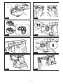
►Fig.6: 1. Action mode changing knob
Rotation only
For drilling in wood, metal or plastic materials, rotate
the action mode changing knob to the symbol.Usea
twist drill bit or wood drill bit.
►Fig.7: 1. Action mode changing knob
Electronic function
The tool is equipped with the electronic functions for
easyoperation.
• Electric brake
This tool is equipped with an electric brake. If the
toolconsistentlyfailstoquicklyceasetofunction
after the switch trigger is released, have the tool
serviced at a Makita service center.
• Constant speed control
The speed control function provides the constant
rotation speed regardless of load conditions.
ASSEMBLY
CAUTION: Always be sure that the tool is
switched o and the battery cartridge is removed
before carrying out any work on the tool.
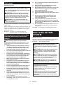
Side grip (auxiliary handle)
CAUTION: Always use the side grip to ensure
safe operation.
CAUTION: After installing or adjusting the
side grip, make sure that the side grip is rmly
secured with the protrusions on the tool are fully
engaged by the grooves on the side grip.
To install the side grip, follow the steps below.
1. Loosen the thumb screw on the side grip.
►Fig.8: 1. Thumb screw
2.
Installthesidegripsothatthegroovesonthegriptin
the protrusions on the tool while pressing the thumb screw.
►Fig.9: 1. Thumb screw
3. Tighten the thumb screw to secure the grip. The
gripcanbexedatdesiredangle.

13 ENGLISH
Installing or removing drill bit
Grease
Cleantheshankendofthebitandapplygreasebefore
installing the bit.
Coat the shank end of the bit beforehand with a small
amount of grease (about 0.5 - 1 g). This chuck lubrica-
tion assures smooth action and longer service life.
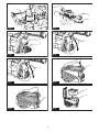
►Fig.10: 1. Shank end 2. Grease
Insert the drill bit into the tool. Turn the drill bit and push
it in until it engages.
Afterinstallingthedrillbit,alwaysmakesurethatthe
drillbitissecurelyheldinplacebytryingtopullitout.
►Fig.11: 1. Drill bit
To remove the drill bit, push the chuck cover down all
thewayandpullthedrillbitout.
►Fig.12: 1. Drill bit 2. Chuck cover
Depth gauge
The depth gauge is convenient for drilling holes of
uniform depth.
Press and hold the lock button, and then insert the
depth gauge into the hole. Make sure that the toothed
side of the depth gauge faces the marking.
►Fig.13: 1. Depth gauge 2. Lock button 3. Marking
4. Toothed side
Adjustthedepthgaugebymovingitbackandforth
whilepressingthelockbutton.Aftertheadjustment,
release the lock button to lock the depth gauge.
NOTE: Make sure that the depth gauge does not
touchthemainbodyofthetoolwhenattachingit.
Dust cup
Optional accessory
Use the dust cup to prevent dust from falling over the
toolandonyourselfwhenperformingoverheaddrilling
operations. Attach the dust cup to the bit as shown in
thegure.Thesizeofbitswhichthedustcupcanbe
attached to is as follows.
Model Bit diameter
Dust cup 5 6 mm - 14.5 mm
Dust cup 9 12 mm - 16 mm
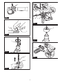
►Fig.14: 1. Dust cup
Dust cup set
Optional accessory
Installing the dust cup set
NOTICE: Do not use the dust cup set when drill-
ing in metal or similar.Itmaydamagethedustcup
setduetotheheatproducedbysmallmetaldustor
similar. Do not install or remove the dust cup set with
thedrillbitinstalledinthetool.Itmaydamagethe
dust cup set and cause dust leak.
Before installing the dust cup set, remove the drill bit
from the tool if installed.
1. Loosen the thumb screw on the side grip.
2. Install the dust cup set so that the claws of the
dustcuptintheslitsonthesidegrip.
►Fig.15: 1. Dust cup set 2. Side grip
3. Install the side grip so that the groove on the grip
tintheprotrusiononthetool.Tightenthethumbscrew
to secure the side grip.
►Fig.16: 1. Side grip 2. Groove 3. Protrusion
NOTE:Ifyouconnectavacuumcleanertothedust
cup set, remove the dust cap before connecting it.
►Fig.17: 1. Dust cap
Removing the drill bit
To remove the drill bit, pull the chuck cover down all the
wayandpullthedrillbitout.
►Fig.18: 1. Drill bit 2. Chuck cover
Removing the dust cup set
To remove the dust cup set, follow the steps below.
1. Loosen the thumb screw on the side grip. Remove
the side grip from the tool.
►Fig.19: 1. Thumb screw
2. Hold the root of dust cup and pull it out.
NOTE:Ifitisdiculttoremovethedustcupset,
removetheclawsofthedustcuponebyoneby
swinging and pulling the root of the dust cup.
►Fig.20: 1. Dust cup
NOTE:Ifthecapcomesofromthedustcupset,
place it back to the original position.
To place the cap back to the original position, follow the
steps below.
1. Turn the bellows counterclockwise and remove it
from the dust cup set attachment unit while the bellows
is unlocked.
►Fig.21: 1. Bellows 2. Attachment unit
2. Set the cap back in place with its lettered side
facing upwards.
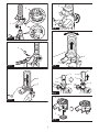
►Fig.22: 1. Cap 2. Attachment unit
3. Besurethatthegroovesaroundthecapwelltin
the lips of the upper opening of the attachment unit.

14 ENGLISH
Tool hanger
Optional accessory
CAUTION: Do not use damaged tool hanger
and screw. Before use, always check for dam-
ages, cracks or deformations, and make sure that
the screw is tightened.
CAUTION: Install or remove the tool hanger
on a stable table or surface. Be sure to use the
screw provided with the tool hanger only. After
installing the tool hanger, make sure that the tool
hanger is securely installed with the screw.
CAUTION: Do not remove the battery car-
tridge while hanging the tool.Thetoolmayfallifthe
screw is not tightened.
Thetoolhangerisintendedforconnectingthelanyard
(tether strap).
Before installing the tool hanger, remove the rubber cap
from the screw hole in the mounting bracket. Insert the
square nut under the bracket. Tighten the tool hanger
with screw in place.
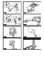
►Fig.23: 1. Rubber cap 2. Mounting bracket
3. Square nut 4. Tool hanger 5. Screw
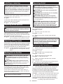
Safety warnings about connecting
lanyard (tether strap) to the tool
hanger
Safety warnings specic for use at height
Read all safety warnings and instructions. Failure
tofollowthewarningsandinstructionsmayresultin
seriousinjury.
1. Always keep the tool tethered when working
"at height". Maximum lanyard length is 2 m.
The maximum permissible fall height for lan-
yard (tether strap) must not exceed 2 m.
2. Use only with lanyards appropriate for this tool
type and rated for at least 6.0 kg.
3. Do not anchor the tool lanyard to anything on
your body or on movable components. Anchor
the tool lanyard to a rigid structure that can
withstand the forces of a dropped tool.
4. Make sure the lanyard is properly secured at
each end prior to use.
5. Inspect the tool and lanyard before each use
for damage and proper function (including
fabric and stitching). Do not use if damaged or
not functioning properly.
6. Do not wrap lanyards around or allow them to
come in contact with sharp or rough edges.
7. Fasten the other end of the lanyard outside
the working area so that a falling tool is held
securely.
8. Attach the lanyard so that the tool will move
away from the operator if it falls. Dropped tools
willswingonthelanyard,whichcouldcauseinjury
or loss of balance.
9. Do not use near moving parts or running
machinery.Failuretodosomayresultinacrush
or entanglement hazard.
10. Do not carry the tool by the attachment device
or the lanyard.
11. Only transfer the tool between your hands
while you are properly balanced.
12. Do not attach lanyards to the tool in a way that
keeps switches or trigger-lock (if supplied)
from operating properly.
13. Avoid getting tangled in the lanyard.
14. Keep lanyard away from the drilling area of the
tool.
15. Use a locking carabiner (multi-action and
screw gate type). Do not use single action
spring clip carabiners.
16. In the event the tool is dropped, it must be
tagged and removed from service, and should
be inspected by a Makita Factory or Authorized
Service Center.
17. Do not hang the tool on your waist. Heated tool
anditsaccessorymaytouchyourskinandburn
injuryresult.
►Fig.24: 1. Tool hanger 2.Lanyard(tetherstrap)
DUST COLLECTION
SYSTEM
Optional accessory
Thedustcollectionsystemisdesignedtocollectdusts
eectivelywhentheconcretedrillingoperation.
►Fig.25: 1.Dustcollectionsystem
CAUTION: The dust collection system is
intended for drilling in concrete only. Do not use
the dust collection system for drilling in metal or
wood.
CAUTION: When using the tool with the dust
collection system, be sure to attach the lter
to the dust collection system to prevent dust
inhalation.
CAUTION: Before using the dust collection
system, check that the lter is not damaged and
the inner pipe is free of dust and foreign matter.
Failuretodosomaycausedustinhalation.
CAUTION: The dust collection system col-
lects the generated dust at a considerable rate,
but not all dust can be collected.
NOTICE: Do not use the dust collection system
for core drilling or chiseling.
NOTICE: Do not use the dust collection system
for metal or wood. Thedustcollectionsystemis
intendedforconcreteonly.
NOTICE: Do not use the dust collection system
for drilling in wet concrete or use this system
in wet environment. Failure to do so may cause
malfunction.

15 ENGLISH
Installing or removing
NOTICE: Before installing the dust collection
system, clean the joint parts of the tool and the
dust collection system. Foreignmattersonthejoint
partsmaycauseitdiculttoinstallthedustcollection
system.Ifanydustremainsontheairduct,thedust
comesintothetoolandcausesjamintheairowor
breakage of the tool.
Toinstallthedustcollectionsystem,insertthetool
completelyintothedustcollectionsystemuntilthetool
is locked in place with a little click.
►Fig.26
Toremovethedustcollectionsystem,pullupthetool
whilepressingthelock-obutton.
►Fig.27: 1.Lock-obutton
Adjusting nozzle position
CAUTION: Do not point the nozzle at yourself
or others when releasing the nozzle by pushing
the guide adjustment button.
Slide in and out the nozzle guide while pressing the
guideadjustmentbutton,andthenreleasethebutton
atanexactpositionwherethetipofthedrillbitsitsjust
behind the front surface of the nozzle.
►Fig.28: 1. Nozzle guide 2.Guideadjustmentbutton
3. Tip of drill bit 4. Front surface of nozzle
Adjusting drilling depths
Drillingdepthscanbeadjustedbychangingthelengths
betweenthedepthadjustmentbuttonandthesupport
armfornozzleguide.Pressandholdthedepthadjust-
mentbuttonandslideittoyourdesiredposition.
►Fig.29: 1.Depthadjustmentbutton2. Nozzle guide
3. Support arm for nozzle guide 4. Drilling
depths
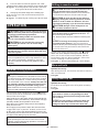
Beating dust on the lter
CAUTION: Do not turn the dial on the dust
case while the dust case is removed from the
dust collection system.Doingsomaycausedust
inhalation.
CAUTION: Always switch o the tool when
turning the dial on the dust case. Turning the dial
whilethetoolisrunningmayresultinthelossof
control of the tool.
Bybeatingthedustonthelterinsidethedustcase,
youcankeepthevacuumeciencyandalsoreduce
the number of times to dispose of the dust.
Turn the dial on the dust case three times after col-
lectingevery50,000mm3ofdustorwhenyoufeelthe
vacuum performance declined.
NOTE: 50,000 mm3 of dust equivalents to drilling 10
holes of ø10 mm and 65 mm depth.
►Fig.30: 1. Dust case 2. Dial
Disposing of dust
CAUTION: Always be sure that the tool is
switched o and the battery cartridge is removed
before carrying out any work on the tool.
CAUTION: Be sure to wear dust mask when
disposing of dust.
CAUTION: Be sure that the tool is completely
stopped when disposing of dust.
CAUTION: Empty the dust case regularly
before the dust case becomes full. Failure to do so
maydecreasethedustcollectionperformanceand
cause dust inhalation.
CAUTION: The performance of dust collection
decreases if the lter in the dust case become
clogged. Replace the lter with new one after
approximately 200 times of dust fulllment as a
guide.Failuretodosomaycausedustinhalation.
1. Remove the dust case while pressing down the
lever of the dust case.
►Fig.31: 1. Lever
2. Open the cover of the dust case.
►Fig.32: 1. Cover
3. Disposeofthedust,andthencleanthelter.
►Fig.33
NOTICE: When cleaning the lter, tap the case
of the lter gently by hand to remove dust. Do not
tap the lter directly; touch the lter with brush
or similar; or blow compressed air on the lter.
Doing so may damage the lter.
Replacing lter of dust case
1. Remove the dust case while pressing down the
lever of the dust case.
►Fig.34: 1. Lever
2. Opentheltercoverofthedustcase.
►Fig.35: 1. Filter cover
3. Removethelterfromtheltercase.
►Fig.36: 1. Filter 2. Filter case
4. Attachanewltertotheltercase,andthen
attachtheltercover.
5. Close the cover of the dust case, and then attach
thedustcasetothedustcollectionsystem.
Replacing sealing cap
1.
Insertaat-bladescrewdriverintooneofthegrooves
placedonthesidesofthenozzlehead.Tilttheat-blade
screwdriver at an angle to squeeze and pop the cube hook of
the sealing cap out. Then peel the rubber edge of the sealing
capawayfromtherimofthenozzleheadopening.
►Fig.37:
1. Sealing cap 2. Cube hook 3. Groove 4. Nozzle head
2. Set one of cube hooks of a new sealing cap into
the lower part of the groove in the nozzle head with a
recessed surface of the sealing cap facing forward.
►Fig.38: 1. Cube hooks 2. Lower part of the groove
3. Sealing cap 4. Recessed surface

16 ENGLISH
3.
Place the other hook into the opposite side, while
repositioningthesealingcaptotnelytothenozzlehead.
►Fig.39: 1. Sealing cap 2. Cube hook 3. Lower part
of the groove 4. Nozzle head 5. Rims
4. Gentlylaytherubberedgeofthesealingcap
down over the rim of the nozzle head opening from
bottom to top.
►Fig.40:
1. Rubber edge 2. Sealing cap 3. Nozzle head
OPERATION
CAUTION: Always use the side grip (auxiliary
handle) and rmly hold the tool by both side grip
and switch handle during operations.
CAUTION: Always make sure that the work-
piece is secured before operation.
CAUTION: Do not pull the tool out forcibly
even the bit gets stuck. Loss of control may
cause injury.
NOTICE: Before using the dust collection sys-
tem with the tool, read the section about the dust
collection system.
NOTE:Ifthebatterycartridgeisinlowtemperature,
thetool’scapabilitymaynotbefullyobtained.Inthis
case,warmupthebatterycartridgebyusingthe
toolwithnoloadforawhiletofullyobtainthetool’s
capability.
►Fig.41
Hammer drilling operation
CAUTION: There is tremendous and sudden
twisting force exerted on the tool/drill bit at the time of
hole break-through, when the hole becomes clogged
with chips and particles, or when striking reinforcing
rods embedded in the concrete. Always use the side
grip (auxiliary handle) and rmly hold the tool by
both side grip and switch handle during opera-
tions.Failuretodosomayresultinthelossofcontrol
ofthetoolandpotentiallysevereinjury.
Set the action mode changing knob to the symbol.
Position the drill bit at the desired location for the hole,
then pull the switch trigger.
Applyfeedforcetotheswitchhandle(mainhandle)for
workingaccuracyandeciency,andholdthesidegrip
(auxiliaryhandle)tokeepbalanceofthetool.
Keepthetoolinpositionandpreventitfromslipping
awayfromthehole.
Donotapplymorepressurewhentheholebecomes
clogged with chips or particles. Instead, run the tool at
anidle,thenremovethedrillbitpartiallyfromthehole.
Byrepeatingthisseveraltimes,theholewillbecleaned
outandnormaldrillingmayberesumed.
NOTE:Eccentricityinthedrillbitrotationmayoccur
while operating the tool with no load. The tool auto-
maticallycentersitselfduringoperation.Thisdoesnot
aectthedrillingprecision.
Drilling in wood or metal
CAUTION: Hold the tool rmly and exert care
when the drill bit begins to break through the
workpiece. There is a tremendous force exerted on
the tool/drill bit at the time of hole break through.
CAUTION: A stuck drill bit can be removed
simply by setting the reversing switch to reverse
rotation in order to back out. However, the tool
may back out abruptly if you do not hold it rmly.
CAUTION: Always secure workpieces in a
vise or similar hold-down device.
NOTICE: Never use “rotation with hammering”
when the drill chuck is installed on the tool. The
drillchuckmaybedamaged.
Also,thedrillchuckwillcomeowhenreversingthe
tool.
NOTICE: Pressing excessively on the tool will
not speed up the drilling. In fact, this excessive
pressurewillonlyservetodamagethetipofyourdrill
bit, decrease the tool performance and shorten the
service life of the tool.
Set the action mode changing knob to the symbol.
Attachthechuckadaptertoakeylessdrillchuckto
which 1/2"-20 size screw can be installed, and then
install them to the tool. When installing it, refer to the
section “Installing or removing drill bit”.
►Fig.42: 1.Drillchuckassembly2. Chuck adapter
Blow-out bulb
Optional accessory
After drilling the hole, use the blow-out bulb to clean the
dust out of the hole.
►Fig.43
Using dust cup set
Optional accessory
Fit the dust cup set against the ceiling when operating
the tool.
►Fig.44
NOTICE: Do not use the dust cup set when drill-
ing in metal or similar. It may damage the dust
cup set due to the heat produced by small metal
dust or similar.
NOTICE: Do not install or remove the dust cup
set with the drill bit installed in the tool. It may
damage the dust cup set and cause dust leak.

17 ENGLISH
MAINTENANCE
CAUTION: Always be sure that the tool is
switched o and the battery cartridge is removed
before attempting to perform inspection or
maintenance.
NOTICE: Never use gasoline, benzine, thinner,
alcohol or the like. Discoloration, deformation or
cracks may result.
To maintain product SAFETY and RELIABILITY,
repairs,anyothermaintenanceoradjustmentshould
beperformedbyMakitaAuthorizedorFactoryService
Centers,alwaysusingMakitareplacementparts.
OPTIONAL
ACCESSORIES
CAUTION: These accessories or attachments
are recommended for use with your Makita tool
specied in this manual.Theuseofanyother
accessories or attachments might present a risk of
injurytopersons.Onlyuseaccessoryorattachment
for its stated purpose.
Ifyouneedanyassistanceformoredetailsregard-
ingtheseaccessories,askyourlocalMakitaService
Center.
• Carbide-tipped drill bits (SDS-Plus carbide-tipped
bits)
• Chuck adapter
• Keylessdrillchuck
• Bit grease
• Depth gauge
• Blow-out bulb
• Dust cup
• Dust cup set
• Dustcollectionsystem
• Tool hanger
• Makitagenuinebatteryandcharger
NOTE:Someitemsinthelistmaybeincludedinthe
toolpackageasstandardaccessories.Theymay
dierfromcountrytocountry.

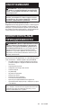
18 SLOVENŠČINA
SLOVENŠČINA (Originalna navodila)
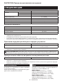
TEHNIČNI PODATKI
Model: DHR183
Vrtalnezmogljivosti Beton 18 mm
Jeklo 13 mm
Les 24 mm
Hitrost brez obremenitve 0 – 1.100 min-1
Udarci na minuto 0 – 5.000 min-1
Celotnadolžina(zBL1860B) 288 mm
Nazivna napetost D.C. 18 V
Netoteža 2,1 – 2,9 kg
Dodatna oprema
Model: DX16
Zmogljivostsesanja 0,24 l/min
Delovni hod Do 105 mm
Primerni vrtalni nastavek Do 165 mm
Netoteža 0,77 kg
• Kernenehnoopravljamoraziskaveinrazvijamosvojeizdelke,selahkotehničnipodatkivtemdokumentu
spremenijobrezobvestila.
• Tehničnipodatkiselahkorazlikujejooddržavedodržave.
• Težaselahkorazlikujegledenapriključke,vključnozakumulatorskobaterijo.Najlažjainnajtežjakombinacijav
skladu s postopkom EPTA 01/2014 sta prikazani v preglednici.
Uporabna akumulatorska baterija in polnilnik
Baterijskivložek BL1815N / BL1820B / BL1830B / BL1840B / BL1850B / BL1860B
Polnilnik DC18RC / DC18RD / DC18RE / DC18SD / DC18SE / DC18SF /
DC18SH / DC18WC
• Nekaterezgorajnavedeneakumulatorskebaterijeinpolnilnikimordavvašidržaviprebivališčanisonavoljo.
OPOZORILO: Uporabljajte le zgoraj navedene akumulatorske baterije in polnilnike. Uporaba drugih
akumulatorskihbaterijinpolnilnikovlahkopovzročitelesnepoškodbein/alipožar.
Priporočen vir napajanja s kablom
Prenosna polnilna enota PDC01
• Vir(i)napajanjaskablom,navedenizgoraj,mordavvašidržaviprebivališčanisonavoljo.
• Preduporaboviranapajanjaskablompreberitenavodilainopozorilneznakenanjem.
Namenska uporaba
Orodjejenamenjenozaudarnovrtanjevopeke,beton
in kamen.
Primernojetudizavrtanjevles,kovino,keramikoin
plastikobrezudarjanja.
Hrup
ObičajnaA-ovrednotenaravenhrupavskladuz
EN62841-2-6:
Model DHR183
Ravenzvočnegatlaka(LpA): 90 dB (A)
Ravenzvočnemoči(LWA): 101 dB (A)
Odstopanje(K):3dB(A)
Model DHR183 z DX16
Ravenzvočnegatlaka(LpA): 90 dB(A)
Ravenzvočnemoči(LWA): 101 dB (A)
Odstopanje(K):3dB(A)
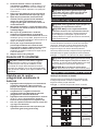
OPOMBA:Navedenevrednostioddajanjahrupaso
bileizmerjenevskladusstandardnimimetodami
testiranjainselahkouporabljajozaprimerjavoorodij.
OPOMBA:Navedenevrednostioddajanjahrupa
selahkouporabljajotudipripredhodnioceni
izpostavljenosti.

19 SLOVENŠČINA
OPOZORILO: Uporabljajte zaščito za sluh.
OPOZORILO: Oddajanje hrupa med dejansko
uporabo električnega orodja se lahko razlikuje od
navedenih vrednosti, odvisno od načina uporabe
orodja in predvsem vrste obdelovanca.
OPOZORILO:
Upravljavec mora za lastno
zaščito poznati varnostne ukrepe, ki temeljijo na
oceni izpostavljenosti v dejanskih pogojih uporabe
(poleg časa proženja je treba upoštevati celoten
delovni cikel, vključno s časom, ko je orodje izklo-
pljeno, in časom, ko deluje v prostem teku).
Vibracije
Vnaslednjitabelijeprikazanaskupnavrednostvibracij
(vektorskavsotatrehosi),določenavskladuzveljav-
nim standardom.
Delovni
način Emisije
vibracij
Odstopanje (K)
Veljavni
standard/
preizkusni
pogoj
Udarno vrta-
njevbeton
(ah, HD)
7,5 m/s21,5 m/s2EN62841-2-6
7,5 m/s21,5 m/s2Priporočeno
praktično
delovanje*
Udarno vrta-
njevbetonz
DX16 (ah, HD)
7,6 m/s21,7 m/s2EN62841-2-6
7,7 m/s21,5 m/s2Priporočeno
praktično
delovanje*
*Preizkusnipogojpriporočenegapraktičnegadelova-
njajevskladusstandardomEN62841-2-6,razenza
naslednje:
• Napretičnem(glavnem)ročajujetrebauporabiti
silopodajanja,dasezagotovitanatančnostin
učinkovitostdelovanja.
• Stranskiročaj/ročico(pomožniročaj)jetreba
držati,daseohraniravnotežjeorodja.
OPOMBA:Navedeneskupnevrednostioddajanja
vibracijsobileizmerjenevskladusstandardnimi
metodamitestiranjainselahkouporabljajozaprimer-
javoorodij.
OPOMBA:Navedeneskupnevrednostioddajanja
vibracijselahkouporabljajotudipripredhodnioceni
izpostavljenosti.
OPOZORILO:
Oddajanje vibracij med
dejansko uporabo električnega orodja se lahko raz-
likuje od navedenih vrednosti, odvisno od načina
uporabe orodja in predvsem vrste obdelovanca.
OPOZORILO:
Upravljavec mora za lastno
zaščito poznati varnostne ukrepe, ki temeljijo na
oceni izpostavljenosti v dejanskih pogojih upo-
rabe (poleg časa proženja je treba upoštevati celo-
ten delovni cikel, vključno s časom, ko je orodje
izklopljeno, in časom, ko deluje v prostem teku).
Izjave o skladnosti
Samo za evropske države
IzjaveoskladnostisovključenevdodatkuAtehnavodil
za uporabo.
VARNOSTNA OPOZORILA
Splošna varnostna opozorila za
električno orodje
OPOZORILO Preberite vsa varnostna opozorila
ter navodila s slikami in tehničnimi podatki, ki so
priloženi temu električnemu orodju.Obneupošteva-
njuspodajnavedenihnavodilobstajanevarnostelek-
tričnegaudara,požarain/alihudihtelesnihpoškodb.
Shranite vsa opozorila in navo-
dila za poznejšo uporabo.
Izraz„električnoorodje“vopozorilihsenanašanavaše
električnoorodje(skablom)alibaterijskoelektrično
orodje(brezkabla).
VARNOSTNA OPOZORILA ZA
BREZŽIČNO VRTALNO KLADIVO
Varnostna navodila za vse načine uporabe
1. Uporabljajte zaščito za sluh.Izpostavljenost
hrupulahkopovzročiizgubosluha.
2. Uporabite pomožne ročaje, če so dobavljeni
z orodjem.Izgubanadzoralahkopovzroči
poškodbeoseb.
3. Če obstaja nevarnost, da bi z rezalnim pripo-
močkom prerezali skrito električno napeljavo,
držite električno orodje na izoliranih držalnih
površinah.Čepridedostikazvodnikipodnape-
tostjo,sopodnapetostjovsineizoliranikovinski
delielektričnegaorodja,zaradičesarlahkoupo-
rabnikutrpielektričniudar.
Varnostna navodila za uporabo dolgih vrtalnih
nastavkov z vrtalnim kladivom
1. Vedno začnite vrtati pri nizki hitrosti, pri čemer
mora biti konica nastavka v stiku z obdelo-
vancem.Privišjihhitrostihselahkonastavek
ukrivi,česeprostovrtibrezstikazobdelovancem,
zaradičesarlahkopridedotelesnihpoškodb.
2. Na orodje pritiskajte samo v smeri nastavka
in ne uporabite prekomerne sile. Nastavki se
lahkoukrivijo,zaradičesarlahkopridedozloma
aliizgubenadzoraterposledičnotudidotelesnih
poškodb.
Dodatna varnostna opozorila
1. Nosite trdo pokrivalo (zaščitno čelado), zašči-
tna očala in/ali obrazno masko. Navadna ali
sončna očala NISO zaščitna očala. Prav tako
je zelo priporočljivo, da nosite protiprašno
masko in debelo oblazinjene rokavice.
2. Pred delom se prepričajte, ali je nastavek trdno
pritrjen.
3. Pri običajnih pogojih orodje oddaja vibracije.
Vijaki lahko hitro popustijo, kar povzroči
poškodbe orodja ali nesrečo. Pred delom
skrbno preverite zategnjenost vijakov.
4. V hladnem vremenu ali če orodja dlje časa
niste uporabljali, počakajte, da se orodje nekaj
časa ogreva, tako da deluje brez obremenitve.
To bo sprostilo mazanje. Brez ustreznega
ogrevanja bo udarno vijačenje oteženo.

20 SLOVENŠČINA
5. Vedno zagotovite, da imate trden oprijem na
podlagi, kjer stojite. Kadar uporabljate orodje
na višini, se prepričajte, da spodaj ni nikogar.
6. Orodje trdno držite z obema rokama.
7. Ne približujte rok premikajočim se delom.
8. Orodja ne pustite delovati brez nadzora.
Dovoljeno ga je uporabljati samo ročno.
9. Med delom ne usmerjajte orodja v druge osebe
v območju. Nastavek lahko odleti in povzroči
hude telesne poškodbe.
10.
Takoj po končani obdelavi se ne dotikajte
nastavka, delov v bližini nastavka ali obdelovanca;
lahko so zelo vroči in povzročijo opekline kože.
11. Nekateri materiali vsebujejo kemikalije, ki so
lahko strupene. Bodite previdni in preprečite
vdihavanje prahu in stik s kožo. Upoštevajte
varnostne podatke dobavitelja materiala.
12. Preden podate orodje drugi osebi, se vedno
prepričajte, da je orodje izklopljeno, akumula-
torska baterija in nastavek pa sta odstranjena.
13.
Pred delom se prepričajte, da v delovnem obmo-
čju ni zakopan noben predmet, na primer elek-
trična, vodovodna ali plinska cev.Česevrtalni
nastavek/dletodotaknetakšnecevi,lahkopovzroči
električniudar,uhajavitokaliuhajanjeplina.
14. Ne uporabljajte orodja brez obremenitve po
nepotrebnem.
SHRANITE TA NAVODILA.
OPOZORILO: NE dovolite, da bi zaradi udob-
nejšega dela ali znanja o uporabi izdelka (prido-
bljenega z večkratno uporabo) opustili strogo
upoštevanje varnostnih zahtev v okviru pravilne
uporabe orodja. ZLORABA ali neupoštevanje var-
nostnih zahtev v teh navodilih za uporabo lahko
povzroči resne telesne poškodbe.
Pomembna varnostna navodila za
akumulatorsko baterijo
1. Pred uporabo baterijskega vložka preberite
vsa navodila in opozorilne oznake na (1) pol-
nilniku akumulatorja, (2) akumulatorju in (3)
izdelku, ki uporablja akumulator.
2. Ne razstavljajte ali spreminjajte akumulatorske
baterije.Stemlahkopovzročitepožar,preko-
mernovročinoalieksplozijo.
3. Če se je čas delovanja občutno skrajšal, takoj
prenehajte uporabljati orodje. V nasprotnem
primeru lahko pride do pregretja, morebitnih
opeklin in celo eksplozije.
4. Če pride elektrolit v stik z očmi, jih sperite s
čisto vodo in takoj poiščite zdravniško pomoč.
Posledica je lahko izguba vida.
5. Ne povzročite kratkega stika baterijskega
vložka:
(1) Ne dotikajte se priključkov s kakršnim
koli prevodnim materialom.
(2) Izogibajte se shranjevanju baterijskega
vložka v vsebniku z drugimi kovinskimi
predmeti kot so žeblji, kovanci itn.
(3) Ne izpostavljajte baterijskega vložka vodi
ali dežju.
Kratek stik akumulatorja lahko povzroči velik
električni tok, pregrevanje, morebitne opekline
in celo okvaro.
6. Ne shranjujte in uporabljajte orodja in akumu-
latorske baterije na mestih, kjer lahko tempera-
tura doseže ali preseže 50 °C (122 °F).
7. Ne sežigajte baterijskega vložka, tudi če je
hudo poškodovan ali v celoti izpraznjen.
Baterijski vložek lahko v ognju eksplodira.
8. Ne pribijajte, režite, drobite, mečite, spuščajte
akumulatorske baterije oziroma ne udarjajte
z akumulatorsko baterijo po trdem predmetu.
Takšnoravnanjelahkopovzročipožar,preko-
mernovročinoalieksplozijo.
9. Ne uporabljajte poškodovanih akumulatorjev.
10. Priložene litij-ionske baterije ustrezajo zahte-
vam zakonodaje v zvezi z nevarnim blagom.
Zakomercialneprevoze,npr.tiste,kijihopravljajo
tretjestrankeincarinskiposredniki,jetrebaupo-
števatiposebnezahtevevzvezizembalažoin
označevanjem.
Med postopkom priprave na odpremo izdelka se
jetrebaposvetovatisstrokovnjakomzanevarne
snovi.Pritemupoštevajtetudipodrobnejšenacio-
nalne predpise.
Odprtestikeoblepitezlepilnimtrakomalijihdru-
gačezaščitite,baterijopazapakirajtetako,dasev
embalažinemorepremikati.
11. Ko odstranjujete akumulatorsko baterijo, jo
vzemite iz orodja in varno zavrzite. Upoštevajte
lokalne uredbe glede odlaganja baterije.
12. Baterije uporabljajte le z izdelki, ki jih določi
Makita.Čenamestitebaterijevneskladneizdelke,
lahkopridedopožara,pregrevanja,eksplozijeali
puščanjaelektrolita.
13. Če orodja dlje časa ne uporabljate, morate iz
njega odstraniti baterijo.
14. Med uporabo in po uporabi lahko akumu-
latorska baterija postane vroča in povzroči
opekline. Z vročimi akumulatorskimi baterijami
ravnajte pazljivo.
15.
Ne dotikajte se priključka orodja takoj po uporabi,
ker se lahko dovolj segreje, da povzroči opekline.
16.
Ne dovolite, da bi se v priključke, odprtine in
utore akumulatorske baterije zlepili ostružki, prah
ali zemlja.Tolahkopovzročipregrevanje,požar,
razpočenjeinokvaroorodjaaliakumulatorskebate-
rijeterprivededoopeklinalidrugihtelesnihpoškodb.
17. Razen če orodje podpira uporabo v bližini
visokonapetostnih električnih vodov, akumula-
torske baterije ne uporabljajte v bližini visoko-
napetostnih električnih vodov.Takšnauporaba
lahkopovzročimotnjevdelovanjualiokvaro
orodjaoziromaakumulatorskebaterije.
18. Baterijo hranite izven dosega otrok.
SHRANITE TA NAVODILA.
POZOR: Uporabljajte le originalne baterije
Makita.ČeuporabljateneoriginalnebaterijeMakita
alibaterije,kisobilespremenjene,lahkopridedo
eksplozijebaterijeinposledičnodopožara,telesnih
poškodbalimaterialneškode.Stakšnouporabo
bostetudirazveljaviligarancijoMakitazaorodjein
polnilnik Makita.
Pagina se încarcă...
Pagina se încarcă...
Pagina se încarcă...
Pagina se încarcă...
Pagina se încarcă...
Pagina se încarcă...
Pagina se încarcă...
Pagina se încarcă...
Pagina se încarcă...
Pagina se încarcă...
Pagina se încarcă...
Pagina se încarcă...
Pagina se încarcă...
Pagina se încarcă...
Pagina se încarcă...
Pagina se încarcă...
Pagina se încarcă...
Pagina se încarcă...
Pagina se încarcă...
Pagina se încarcă...
Pagina se încarcă...
Pagina se încarcă...
Pagina se încarcă...
Pagina se încarcă...
Pagina se încarcă...
Pagina se încarcă...
Pagina se încarcă...
Pagina se încarcă...
Pagina se încarcă...
Pagina se încarcă...
Pagina se încarcă...
Pagina se încarcă...
Pagina se încarcă...
Pagina se încarcă...
Pagina se încarcă...
Pagina se încarcă...
Pagina se încarcă...
Pagina se încarcă...
Pagina se încarcă...
Pagina se încarcă...
Pagina se încarcă...
Pagina se încarcă...
Pagina se încarcă...
Pagina se încarcă...
Pagina se încarcă...
Pagina se încarcă...
Pagina se încarcă...
Pagina se încarcă...
Pagina se încarcă...
Pagina se încarcă...
Pagina se încarcă...
Pagina se încarcă...
Pagina se încarcă...
Pagina se încarcă...
Pagina se încarcă...
Pagina se încarcă...
Pagina se încarcă...
Pagina se încarcă...
Pagina se încarcă...
Pagina se încarcă...
Pagina se încarcă...
Pagina se încarcă...
Pagina se încarcă...
Pagina se încarcă...
Pagina se încarcă...
Pagina se încarcă...
Pagina se încarcă...
Pagina se încarcă...
Pagina se încarcă...
Pagina se încarcă...
Pagina se încarcă...
Pagina se încarcă...
Pagina se încarcă...
Pagina se încarcă...
Pagina se încarcă...
Pagina se încarcă...
Pagina se încarcă...
Pagina se încarcă...
Pagina se încarcă...
Pagina se încarcă...
Pagina se încarcă...
Pagina se încarcă...
Pagina se încarcă...
Pagina se încarcă...
Pagina se încarcă...
Pagina se încarcă...
Pagina se încarcă...
Pagina se încarcă...
Pagina se încarcă...
Pagina se încarcă...
Pagina se încarcă...
Pagina se încarcă...
Pagina se încarcă...
Pagina se încarcă...
Pagina se încarcă...
Pagina se încarcă...
Pagina se încarcă...
Pagina se încarcă...
Pagina se încarcă...
Pagina se încarcă...
-
 1
1
-
 2
2
-
 3
3
-
 4
4
-
 5
5
-
 6
6
-
 7
7
-
 8
8
-
 9
9
-
 10
10
-
 11
11
-
 12
12
-
 13
13
-
 14
14
-
 15
15
-
 16
16
-
 17
17
-
 18
18
-
 19
19
-
 20
20
-
 21
21
-
 22
22
-
 23
23
-
 24
24
-
 25
25
-
 26
26
-
 27
27
-
 28
28
-
 29
29
-
 30
30
-
 31
31
-
 32
32
-
 33
33
-
 34
34
-
 35
35
-
 36
36
-
 37
37
-
 38
38
-
 39
39
-
 40
40
-
 41
41
-
 42
42
-
 43
43
-
 44
44
-
 45
45
-
 46
46
-
 47
47
-
 48
48
-
 49
49
-
 50
50
-
 51
51
-
 52
52
-
 53
53
-
 54
54
-
 55
55
-
 56
56
-
 57
57
-
 58
58
-
 59
59
-
 60
60
-
 61
61
-
 62
62
-
 63
63
-
 64
64
-
 65
65
-
 66
66
-
 67
67
-
 68
68
-
 69
69
-
 70
70
-
 71
71
-
 72
72
-
 73
73
-
 74
74
-
 75
75
-
 76
76
-
 77
77
-
 78
78
-
 79
79
-
 80
80
-
 81
81
-
 82
82
-
 83
83
-
 84
84
-
 85
85
-
 86
86
-
 87
87
-
 88
88
-
 89
89
-
 90
90
-
 91
91
-
 92
92
-
 93
93
-
 94
94
-
 95
95
-
 96
96
-
 97
97
-
 98
98
-
 99
99
-
 100
100
-
 101
101
-
 102
102
-
 103
103
-
 104
104
-
 105
105
-
 106
106
-
 107
107
-
 108
108
-
 109
109
-
 110
110
-
 111
111
-
 112
112
-
 113
113
-
 114
114
-
 115
115
-
 116
116
-
 117
117
-
 118
118
-
 119
119
-
 120
120


Makita DHR183 Manual de utilizare
- Categorie
- Unelte electrice
- Tip
- Manual de utilizare
Lucrări înrudite
-
Makita DHR263 Manual de utilizare
-
Makita HR007G Cordless Combination Hammer Manual de utilizare
-
-
-
-
-
-
Makita DHP485 Manual de utilizare
-