Yamaha MCR-E810 Manual de utilizare
- Categorie
- DVD playere
- Tip
- Manual de utilizare

YAMAHA ELECTRONICS CORPORATION, USA
6660 ORANGETHORPE AVE., BUENA PARK, CALIF. 90620, U.S.A.
YAMAHA CANADA MUSIC LTD.
135 MILNER AVE., SCARBOROUGH, ONTARIO M1S 3R1, CANADA
YAMAHA ELECTRONIK EUROPA G.m.b.H.
SIEMENSSTR. 22-34, 25462 RELLINGEN BEI HAMBURG, GERMANY
YAMAHA ELECTRONIQUE FRANCE S.A.
RUE AMBROISE CROIZAT BP70 CROISSY-BEAUBOURG 77312 MARNE-LA-VALLEE CEDEX02, FRANCE
YAMAHA ELECTRONICS (UK) LTD.
YAMAHA HOUSE, 200 RICKMANSWORTH ROAD WATFORD, HERTS WD18 7GQ, ENGLAND
YAMAHA SCANDINAVIA A.B.
J A WETTERGRENS GATA 1, BOX 30053, 400 43 VÄSTRA FRÖLUNDA, SWEDEN
YAMAHA MUSIC AUSTRALIA PTY, LTD.
17-33 MARKET ST., SOUTH MELBOURNE, 3205 VIC., AUSTRALIA
©
2006 All rights reserved.
OWNER'S MANUAL
MODE D'EMPLOI
BEDIENUNGSANLEITUNG
BRUKSANVISNING
MANUALE DI ISTRUZIONI
MANUAL DE INSTRUCCIONES
GEBRUIKSAANWIJZING
G
AMPLI-TUNER/LECTEUR DE DVD
RECEIVER/DVD PLAYER
Printed in China WH45470-2
LIST OF REMOTE CONTROL CODES
LISTE DES CODES DE COMMANDE
LISTE DER FERNBEDIENUNGSCODES
LISTA ÖVER FJÄRRSTYRNINGSKODER
LISTA DEI CODICI DI TELECOMANDO
LISTA DE CÓDIGOS DE MANDO A DISTANCIA
LIJST MET AFSTANDSBEDIENINGSCODES
СПИСОК КОДОВ ДИСТАНЦИОННОГО УПРАВЛЕНИЯ
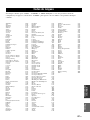
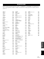
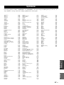
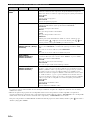
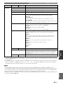
TV
Admiral 292/293/216
Aiwa 294/276/283/284
Akai 295/296
Alba 296
AOC 297
Bell & Howell 292
Bestar 298
Blaupunkt 229/222
Blue sky 298
Brandt 223
Brocsonic 297
Bush 296
By Design 201/202
Clatronic 298
Craig 224
Croslex 225/298
Curtis Mathis 297/226
Daewoo 297/298/224/227/
228
Dayton 239
Dwin 293/281
Emerson 297/224/239/232
Ferguson 223/265/266
First line 298
Fisher 295/233
Fraba 298
Fujitsu 289
Funai 277/278
GE 293/297/234/235/
236
Goodmans 296/298/223
Grundig 229/238/249
Hitachi 297/239/242/243/
285
ICE 296
Irradio 296
Itt/Nokia 244/245
JC Penny 293/297/234/237
JVC (Victor) 296/246/247/286
Kendo 298
KTV 297/239
LG/Goldstar 297/298/239/237
Loewe 298/248
LXI 293/297/225/226/
233/298
Magnavox 297/225/239/298
Marantz 298/210
Matsui 295
Medion 203/204/298
Memorex 297/216
Mitsubishi 299/297/259/287
Nad 226/255
NEC 297/252/282
Nokia 244/245
Nokia Oceanic 245
Nordmende 265/266
Onwa 296
Panasonic 234/235/236/253/
288/211
Philco 297/225/239/298
Philips 225/205/298
Pioneer 226/235/254/255/
268
Portland 297/256
Proscan 293/221
Proton 297/250/260/270
Quasar 234/235
Radio Shack 299/293/297
RCA 293/297/234/256/
257/258/221
SABA 223/269/265/266
Sampo 281/297/280
Samsung 297/239/248/262/
275
Sanyo 295/233/279/272/
273/274/212
Schneider 296
Scott 297
Sharp 292/239/232/213
Siemens 229
Signature 216/292
Sony 263/214
Sylvania 297/225/298
Symphonic 217/218/219
Telefunken 269/264/265/266
Thomson 223/266
Toshiba 292/226/267/215
Videch 297/242
Wards 297/239/232/216
Yamaha 299/292/242/285/
287/253
Zenith 216/261/271
MCR-E810_G_cv_new.fm Page 1 Wednesday, August 30, 2006 6:10 PM

i
CAUTION VISIBLE AND INVISIBLE LASER RADIATION
WHEN OPEN. AVOID EXPOSURE TO BEAM.
ADVARSEL SYNLIG OG USYNLIG LASERSTRÅLING
VED ÅBNING. UNDGÅ UDSÆTTELSE FOR STRÅLING.
ADVARSEL SYNLIG OG USYNLIG LASERSTRÅLING
NÅR DEKSEL ÅPNES. UNNGÅ EKSPONERING FOR
STRÅLEN.
VARNING SYNLIG OCH OSYNLIG LASERSTRÅLNING
NÄR DENNA DEL ÄR ÖPPNAD. BETRAKTA EJ
STRÅLEN.
VARO! AVATTAESSA OLET ALTTIINA NÄKYVÄLLE JA
NÄKYMÄTTÖMÄLLE LASER SÄTEILYLLE. ÄLÄ KATSO
SÄTEESEEN.
VORSICHT SICHTBARE UND UNSICHTBARE
LASERSTRAHLUNG WENN ABDECKUNG GEÖFFNET.
NICHT DEM STRAHL AUSSETSEN.
DANGER VISIBLE AND INVISIBLE LASER RADIATION
WHEN OPEN. AVOID DIRECT EXPOSURE TO BEAM.
ATTENTION RAYONNEMENT LASER VISIBLE ET
INVISIBLE EN CAS D’OUVERTURE. EXPOSITION
DANGEREUSE AU FAISCEAU.
CLASS 1 LASER PRODUCT
LASER KLASSE 1 PRODUKT
LUOKAN 1 LASERLAITE
KLASS 1 LASER APPARAT
PRODUIT LASER DE CLASSE 1
AVOID DIRECT EXPOSURE TO THE BEAM
INVISIBLE LASER RADIATION WHEN OPEN
DANGER:
DO NOT STARE INTO BEAM
INVISIBLE LASER RADIATION WHEN OPEN
CAUTION:
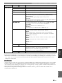
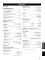
LASER
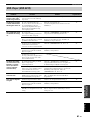
Type Semiconductor laser GaAlAs
Wave length 650 nm (DVD)
780 nm (VCD/CD)
Output Power 7 mW (DVD)
10 mW (VCD/CD)
Beam divergence 60 degrees
CAUTION
Use of controls or adjustments or performance of
procedures other than those specified herein may result
in hazardous radiation exposure.
LASER
Type Laser à semi-conducteur
GaAlAs
Longueur d’onde 650 nm (DVD)
780 nm (VCD/CD)
Puissance de sortie 7 mW (DVD)
10 mW (VCD/CD)
Divergence de faisceau 60 degrés
AVERTISSEMENT
L’utilisation de commandes et l’emploi de réglages ou
de méthodes autres que ceux décrits ci-dessous,
peuvent entraîner une exposition à un rayonnement
dangereux.
LASER
Typ Halbleiter-GaAlAs-Laser
Wellenlänge 650 nm (DVD)
780 nm (VCD/CD)
Ausgangsleistung 7 mW (DVD)
10 mW (VCD/CD)
Strahlstreuung 60 Grad
VORSICHT
Die Verwendung von Bedienelementen oder die
Einstellung bzw. die Ausführung von anderen als in
dieser Anleitung beschriebenen Vorgängen kann zu
Gefährdung durch gefährliche Strahlung führen.
LASER
Typ Halvledarlaser GaAlAs
Våglängd 650 nm (DVD)
780 nm (VCD/CD)
Uteffekt 7 mW (DVD)
10 mW (VCD/CD)
Stråldivergens 60 grader
OBSERVERA
Användning av reglage eller justeringar eller utförande
av åtgärder på annat sätt än så som beskrivs häri kan
resultera i farlig strålning.

ii
DK
Advarsel:
Laserrudstråling ved åbning når sikkerhesafbrydere er ude
af funktion. Undgå u tsættelse for stråling.
Bemærk:
Netafbryderen STANDBY/ON er sekundært indkoblet og
afbryder ikke strømmen fra nette. Den indbyggede netdel
er derfor tilsluttet til lysnettet så længe netstikket sidder i
stikkontakten.
N
Observer:
Nettbryteren STANDBY/ON er sekundert innkoplet. Den
innebygdenetdelen er derfor ikke frakoplet nettet så lenge
apparatet er tilsluttet nettkontakten.
S
Klass 1 laserapparat
Varning!
Om apparaten används på annat sätt än i denna
bruksanvisning specificerats, kann användaren utsättas för
laserstrålning, som översjruder gränsen för läserklass 1.
Observera!
Strömbrytaren STANDBY/ON är sekundärt kopplad och inte
bryter strömmen fråan nätet Den inbyggda nätdelen är
därför ansluten till elnätet så länge stickproppen sitter i v
ägguttaget.
SF
Luokan 1 laserlaite + Klass 1 laserapparat
Varoitus!
Laitteen käyttäminen muulla kuin tässä käyttöohjeessa
mainitulla tavalla saattaa altistaa käyttäjän
turvallisuusluokan 1 ylittävälle lasersäleilille.
Huom.
Toiminnanvalitsin STANDBY/ON on kytketty toisiopuolelle,
eikä se kytke laitetta irti sähköverkosta. Sisäänrakennettu
verkko-osa on kytkettynä sähköverkkoon aina silloin, kun
pistoke on pistorasiassa.
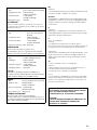
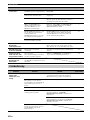
LASER
Tipo
Laser a semiconduttori al GaAlAs
Lunghezza d'onda 650 nm (DVD)
780 nm (VCD/CD)
Potenza d'uscita 7 mW (DVD)
10 mW (VCD/CD)
Divergenza raggi 60 gradi
ATTENZIONE
L’uso di controlli, regolazioni, operazioni o procedure non
specificati in questo manuale possono risultare in esposizione
a radiazioni pericolose.
LÁSER
Tipo Láser de semiconductor
GaAlAs
Longitud de onda 650 nm (DVD)
780 nm (VCD/CD)
Potencia de salida 7 mW (DVD)
10 mW (VCD/CD)
Divergencia del rayo láser 60 grados
PRECAUCIÓN
El uso de los controles, los ajustes o los
procedimientos que no se especifican enste manual
pueden causar una exposición peligrosa a la radiación.
LASER
Type GaAlAs Halfgeleiderlaser
Golflengte 650 nm (DVD)
780 nm (VCD/CD)
Uitgangsvermogen 7 mW (DVD)
10 mW (VCD/CD)
Uitwijking straal 60 graden
LET OP
Gebruik van bedieningsorganen, instellingen of
procedures anders dan beschreven in dit document kan
leiden tot blootstelling aan gevaarlijke stralen.
ЛАЗЕР
Тип
Полупроводниковый лазер GaAlAs
Длина волны 650 nm (DVD)
780 nm (VCD/CD)
Выходное напряжение
7 mW (DVD)
10 mW (VCD/CD)
Отклонение луча 60 градусов
ПРЕДОСТЕРЕЖЕНИЕ
Использование органов управления или
произведение настроек или выполнение процедур, не
указанных в данной инструкции, может отразиться на
выделении опасной радиации.
VARO!
AVATTAESSA JA SUOJALUKITUS OHITETTAESSA
OLET ALTTIINA NÄKYMÄTTÖMÄLLE
LASERSÄTEILYLLE. ÄLÄ KATSO SÄTEESEEN.
VARNING!
OSYNLIG LASERSTRÅLNING NÄR DENNA DEL ÄR
ÖPPNAD OCH SPÄRREN ÄR URKOPPLAD.
BETRAKTA EJ STRÅLEN.

iii
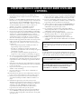
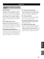
1 To assure the finest performance, please read this manual
carefully. Keep it in a safe place for future reference.
2 Install this unit (RX-E810 and DVD-E810) in a well ventilated,
cool, dry, clean place with at least 10 cm on the top (2.5 cm for
DVD-E810), 10 cm on the left and right, and 10 cm at the back of
this unit — away from direct sunlight, heat sources, vibration,
dust, moisture, and/or cold.
3 Locate this unit away from other electrical appliances, motors, or
transformers to avoid humming sounds.
4 Do not expose this unit to sudden temperature changes from cold
to hot, and do not locate this unit in an environment with high
humidity (i.e. a room with a humidifier) to prevent condensation
inside this unit, which may cause an electrical shock, fire,
damage to this unit, and/or personal injury.
5 Avoid installing this unit where foreign object may fall onto this
unit and/or this unit may be exposed to liquid dripping or
splashing. On the top of this unit, do not place:
– Other components, as they may cause damage and/or
discoloration on the surface of this unit.
– Burning objects (i.e. candles), as they may cause fire, damage
to this unit, and/or personal injury.
– Containers with liquid in them, as they may fall and liquid
may cause electrical shock to the user and/or damage to this
unit.
6 Do not cover this unit with a newspaper, tablecloth, curtain, etc.
in order not to obstruct heat radiation. If the temperature inside
this unit rises, it may cause fire, damage to this unit, and/or
personal injury.
7 Do not plug in this unit to a wall outlet until all connections are
complete.
8 Do not operate this unit upside-down. It may overheat, possibly
causing damage.
9 Do not use force on switches, knobs and/or cords.
10 When disconnecting the power cable from the wall outlet, grasp
the plug; do not pull the cable.
11 Do not clean this unit with chemical solvents; this might damage
the finish. Use a clean, dry cloth.
12 Only voltage specified on this unit must be used. Using this unit
with a higher voltage than specified is dangerous and may cause
fire, damage to this unit, and/or personal injury. YAMAHA will
not be held responsible for any damage resulting from use of this
unit with a voltage other than specified.
13 Do not attempt to modify or fix this unit. Contact qualified
YAMAHA service personnel when any service is needed.
The cabinet should never be opened for any reasons.
14 When not planning to use this unit for long periods of time (i.e.
vacation), disconnect the AC power plug from the wall outlet.
15 Be sure to read the “Troubleshooting” section on common
operating errors before concluding that this unit is faulty.
16 Before moving this unit, press STANDBY/ON to set this unit in
standby mode, and disconnect the AC power plug from the wall
outlet.
17 Condensation will form when the surrounding temperature
changes suddenly. Disconnect the power cable from the outlet,
then leave the unit alone.
18 When using the unit for a long time, the unit may become warm.
Turn the power off, then leave the unit alone for cooling.
19 Install this unit near the wall outlet and where the AC power plug
can be reached easily.
DANGER
When this unit is plugged to the wall outlet, do not place your
eyes close to the opening of the disc tray and other openings to
look into inside.
■ For U.K. customers
If the socket outlets in the home are not suitable for the plug
supplied with this appliance, it should be cut off and an
appropriate 3 pin plug fitted. For details, refer to the instructions
described below.
The plug severed from the mains lead must be destroyed, as a
plug with bared flexible cord is hazardous if engaged in a live
socket outlet.
■ Special Instructions for U.K. Model
CAUTION: READ THIS BEFORE OPERATING YOUR UNIT.
This unit is not disconnected from the AC power source as
long as it is connected to the wall outlet, even if this unit itself
is turned off. This state is called the standby mode. In this
state, this unit is designed to consume a very small quantity of
power.
The laser component in this product is capable of emitting
radiation exceeding the limit for Class 1.
WARNING
TO REDUCE THE RISK OF FIRE OR ELECTRIC SHOCK,
DO NOT EXPOSE THIS APPLIANCE TO RAIN OR
MOISTURE.
Note
IMPORTANT
THE WIRES IN MAINS LEAD ARE COLOURED IN
ACCORDANCE WITH THE FOLLOWING CODE:
Blue: NEUTRAL
Brown: LIVE
As the colours of the wires in the mains lead of this appa-
ratus may not correspond with the coloured markings
identifying the terminals in your plug, proceed as follows:
The wire which is coloured BLUE must be connected to
the terminal which is marked with the letter N or coloured
BLACK. The wire which is coloured BROWN must be
connected to the terminal which is marked with the letter L
or coloured RED.
Making sure that neither core is connected to the earth
terminal of the three pin plug.

1 En
English
PREPARATIONINTRODUCTION
TUNER
OPERATIONS
OTHER
OPERATIONS
ADDITIONAL
INFORMATION
BASIC
OPERATIONS
Features .................................................................. 2
Supplied Accessories ............................................. 2
Controls and Functions......................................... 3
Receiver (RX-E810) .................................................. 3
DVD player (DVD-E810).......................................... 6
Remote control........................................................... 8
Connecting the System ........................................ 12
Connecting a TV.................................................. 14
Connecting Antennas .......................................... 15
Connecting the AM loop antenna ............................ 15
Connecting the FM antenna..................................... 15
Connecting External Components ..................... 16
Connecting an MD player or a tape deck ................ 16
Connecting an MD recorder or a CD recorder ........ 16
Connecting a YAMAHA iPod universal dock ........ 17
Connecting the Power Cables............................. 18
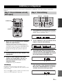
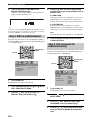
Setting the System................................................ 19
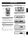
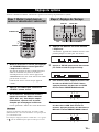
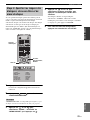
Step 1: Turn on the power and select
the DVD input ..................................................... 19
Step 2: Adjust the clock........................................... 19
Step 3: Set the aspect ratio....................................... 20
Step 4: Set the OSD language.................................. 20
Step 5: Set the the default audio, subtitle,
and disc menu languages ..................................... 21
Basic Receiver Operations.................................. 22
Changing the front panel display settings................ 23
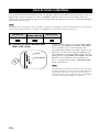
Supported Disc Types.......................................... 24
Basic Disc Playback Operations......................... 25
Repeating disc playback (Repeat Play) ................... 26
Playing back randomly (Shuffle Play)..................... 26
Specifying an elapsed time for playback
(Time Search) ...................................................... 27
Specifying a preview picture for playback
(Scan Search)....................................................... 28
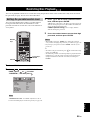
Customizing playback order (Program Play) .......... 29
Selecting audio and subtitle languages/
audio channel settings. ........................................ 30
Zooming the picture................................................. 30
Selecting a viewing angle ........................................ 31
Operating the disc menu .......................................... 31
Playing back MP3/WMA/JPEG/DivX discs ........... 32
Viewing or changing playback settings on the TV
(OSD menu) ........................................................ 34
Restricting Disc Playback ................................... 35
Setting the parental control level ............................. 35
Locking a disc.......................................................... 36
Changing the password............................................ 36
FM/AM Tuning .................................................... 37
Automatic tuning ..................................................... 37
Manual tuning.......................................................... 37
Automatic preset tuning........................................... 38
Manual preset tuning ............................................... 39
Selecting preset stations........................................... 39
Radio Data System Tuning
(U.K. and Europe Models Only)..................... 40
Selecting the Radio Data System program .............. 40
Displaying the Radio Data System information ...... 41
Setting the Timer.................................................. 43
Setting the clock timer............................................. 43
Setting the sleep timer ............................................. 44
Setting the auto-standby mode............................ 45
Controlling External Components...................... 46
Available operations ................................................ 46
Setting remote control codes ................................... 48
Using iPod ............................................................... 49
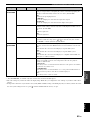
Configuring the DVD Player Settings
(Setup Menu) .................................................... 51
Setup menu items..................................................... 52
Resetting the DVD player settings .......................... 56
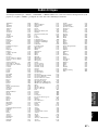
Language Codes ................................................... 57
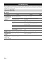
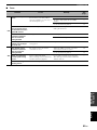
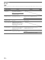
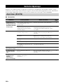
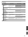
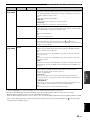
Troubleshooting.................................................... 58
Receiver (RX-E810) ................................................ 58
DVD player (DVD-E810)........................................ 61
Remote control ........................................................ 62
Notes on Discs ....................................................... 63
Disc information ...................................................... 63
Handling a disc ........................................................ 64
Glossary................................................................. 65
Audio information ................................................... 65
Video information.................................................... 66
Copyright and logo marks ....................................... 66
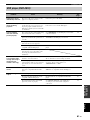
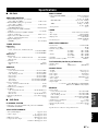
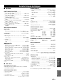
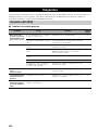
Specifications ........................................................ 67
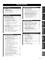
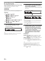
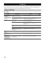
Contents
INTRODUCTION
PREPARATION
BASIC OPERATIONS
TUNER OPERATIONS
OTHER OPERATIONS
ADDITIONAL INFORMATION

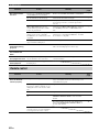
FEATURES
2 En
Receiver (RX-E810)
• Maximum RMS output power per channel
65W + 65W (6 Ω, 1 kHz, 1%THD)
• 40-station FM/AM preset tuning
• iPod dock terminal
• Pure Direct mode
DVD player (DVD-E810)
• Plays DVDs, Video CDs, Audio CDs, MP3 CDs,
WMA CDs, DivX CDs and JPEG CDs.
• Progressive-scan video output
• Optical and coaxial digital output jacks
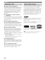
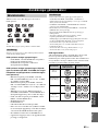
■ About this manual
• In this manual, “RX-E810” is described as “receiver” and “DVD-E810” is described as “DVD player”.
• This manual describes how to operate the system using a remote control except when it is not available. Some of these operations are
also available using the front panel buttons.
• Remote control descriptions and illustrations in this manual are based on the U.K. and Europe models unless otherwise specified.
• y indicates a tip for your operation.
• Notes contain important information about safety and operating instructions.
• This manual is printed prior to production. Design and specifications are subject to change in part as a result of improvements, etc. In
case of differences between the manual and the product, the product has priority.
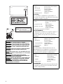
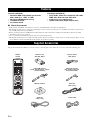
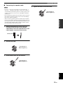
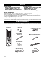
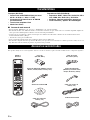
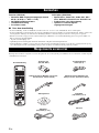
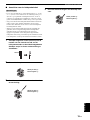
This product includes the following accessories. Before connecting this system, make sure you received all of the following parts.
Features
Supplied Accessories
STANDBY/ON
POWER
TV
1234
56
90
78
SCAN DIMMER
A-B
FREQ/TEXT
PTY SEEK
MODE START
PROG
SHUFFLETV INPUT
ON SCREEN MENU
PRESET
ENTER
A-E
DISPLAY
SLEEP
DVD/CD TUNER BAND
TAPE/MD
SUBTITLE ANGLE ZOOM AUDIO
AUX/TV DOCK
A-E
INFO.
SET UP
TV VOL VOLUME
TOP MENU
/RETURN
TV CH
REPEAT
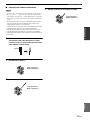
Indoor FM antenna
(U.K., Europe, Australia,
and Korea models)
System control
cable (0.6 m)
AM loop antenna
Batteries (x2)
(AA, R06, UM-3)
Remote
control
Video pin
cable (1.5 m)
Audio pin
cable (1.5 m)
Indoor FM antenna
(U.S.A., Canada, China, Taiwan,
and Asia models)
Power cable

3 En
English
INTRODUCTION
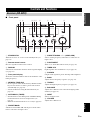
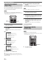
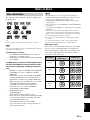
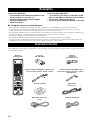
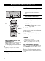
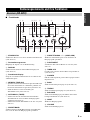
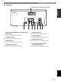
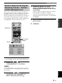
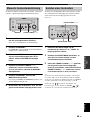
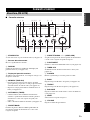
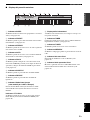
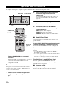
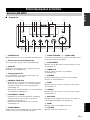
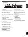
■ Front panel
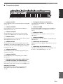
1 STANDBY/ON
Turns the receiver on or sets it to the standby mode (see
page 19).
2 Remote control sensor
Receives signals from the remote control.
3 DISPLAY
Switches the information shown in the front panel display
(see page 23).
4 Front panel display
Shows the various infomaiton such as the clock time or the
tuning frequency.
5 MEMORY (TIME ADJ)
• Stores a preset station in the memory. Hold down this
key for more than 2 seconds to preset radio stations
automatically (see page 38).
• Sets the clock before using the timer function (see
page 19).
6 AUTO/MAN’L (TIMER)
• Switches between Auto Tuning mode and Manual Tuning
mode when tuner is selected as an input source (see
page 37).
• Turns the clock timer function on or off (see page 43).
7 PRESET/BAND
Switches between FM, AM, and the preset mode when
tuner is selected as an input source.
8 PRESET/TUNING d / u (HOUR, MIN)
Selects a tuning frequency when tuner is selected as an
input source.
9 PURE DIRECT
Turns on or off the Pure Direct mode (see page 22).
0 TIMER LED
Lights up when the clock timer is on (see page 43).
A PHONES
Outputs audio signals for private listening with headphones.
B BASS
Adjusts the low frequency responce (see page 22).
C TREBLE
Adjusts the high frequency responce (see page 22).
D BALANCE
Adjusts the volume level of each left and right speaker
channel (see page 22).
E INPUT
Selects an input source.
F VOLUME
Adjusts the volume level.
Controls and Functions
Receiver (RX-E810)
MIN MAX
VOLUME
INPUT
BALANCE
LR
TREBLEBASS
PHONES
STANDBY/ON
TIMER
DISPLAY MEMORY
NATURAL SOUND STEREO RECEIVER RX-E810
PRESET/BAND
PRESET/TUNING
PURE DIRECT
HOURTIMER
TIME ADJ
MIN
AUTO/MAN'L
12 345 6 7 8 9
A0BCDE F

4 En
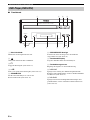
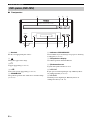
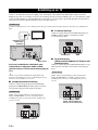
Controls and Functions
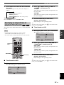
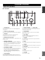
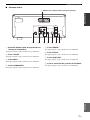
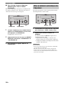
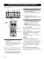
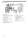
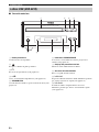
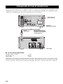
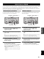
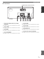
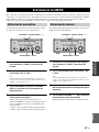
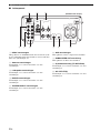
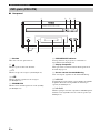
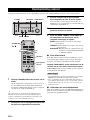
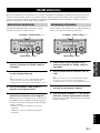
■ Rear panel
1 DOCK terminal
Use to connect a YAMAHA iPod universal dock (such as
YDS-10 sold separately) where your iPod can be stationed
(see page 17).
2 Antenna terminals
See page 15 for connection information.
3 Speaker terminals
See page 13 for connection information.
4 DVD/CD jacks
See page 12 for connection information.
5 TAPE/MD IN/OUT jacks
See page 16 for connection information.
6 AUX jacks
Use to connect the external components.
7 SUBWOOFER OUT jack
Use to connect the subwoofer.
8 System connector (TO DVD-E810) jack
See page 12 for connection information.
9 AC OUTLET(S)
See page 18 for connection information.
LR
LR
AC OUTLETS
SWITCHED
MAINS
SPEAKERS
DOCK
DVD/CD
TAPE/MD
AUX
OUT
IN
FM
GND
AM
ANTENNA
6
MIN / SPEAKER
TO DVD-E810
SUBWOOFER
OUT
100W MAX. TOTAL
75
UNBAL.
12 3
64
578 9
(Europe model)

5 En
Controls and Functions
English
INTRODUCTION
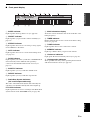
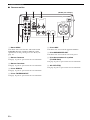
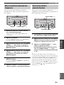
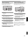
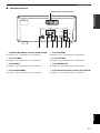
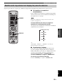
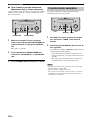
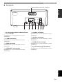
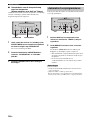
■ Front panel display
1 SLEEP indicator
Lights up when the sleep timer is on (see page 44).
2 PRESET indicator
Lights up when you preset radio stations manually (see
page 39).
3 STEREO indicator
Lights up when the receiver is receiving a strong signal
from an FM stereo broadcast.
4 AUTO indicator
Lights up when the receiver is in the Auto Tuning mode
(see page 38).
5 DOCK indicator
Lights up when you station your iPod in a YAMAHA iPod
universal dock (such as YDS-10 sold separately)
connected to the DOCK terminal of the receiver (see
page 17).
6 SHUFFLE indicator
Lights up when you set your iPod in shuffle mode.
7 REPEAT indicator
Lights up when you set your iPod in repeat mode.
8 Radio Data System indicators
(U.K. and Europe models only)
The name of the Radio Data System data offered by the
currently received Radio Data System station lights up.
PTY HOLD indicator
Lights up when the receiver is seaching for the Radio Data
System stations in the PTY SEEK mode (see page 40).
9 Multi-information display
Shows the various infomaiton such as the clock time or the
tuning frequency.
0 TIMER indicator
Flashes when the the receiver is in the clock timer setting
mode (see page 43).
A TUNED indicator
Lights up when the receiver is tuned into a station.
B MEMORY indicator
Lights up or flashes when you preset radio stations.
C iPod menu indicators
Light up the iPod menu currently selected (see page 49).
D iPod operation indicators
Show operable cursor keys when operating the iPod menu
with the menu browse mode (see page 49).
GENRES
SONGS
ALBUMS
ARTISTSPLAYLISTS
MEMORY
TUNED
TIMER
SLEEP
STEREO
AUTO
DOCK
SHUFFLE
REPEAT
PS
PTY RT CT PTY
HOLD
PRESET
1 234567 8
0AB C
D
9

6 En
Controls and Functions
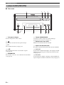
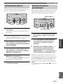
■ Front panel
1 Disc tray
Holds a disc to be played back.
2
Opens and closes the disc tray.
3 s
Stops playback (see page 25).
4 h/e
Starts or pauses playback (see page 25).
5 STANDBY/ON
Turns the DVD player on or sets it to the standby mode
(see page 22).
6 PROGRESSIVE indicator
Lights up when the progressive scan mode is on (see
page 54).
7 Front panel display
Shows the current status of the DVD player.
8 Remote control sensor
Receives signals from the remote control.
9 b/w
Skips to the begining of the current chapter/track. Press
and hold to fast reverse (see page 25).
0 f/a
Skips to the next chapter/track. Press and hold to fast
forward (see page 25).
DVD player (DVD-E810)
STANDBY/ON
PROGRESSIVE
NATURAL SOUND DVD PLAYER DVD-E810
6 7589
2
13
4
0

7 En
Controls and Functions
English
INTRODUCTION
■ Rear panel
1 AV terminal (U.K. and Europe models only)
See page 14 for connection information.
2 S VIDEO jack
See page 14 for connection information.
3 VIDEO jack
See page 14 for connection information.
4 COMPONENT jacks
See page 14 for connection information.
5 COAXIAL jack
See page 16 for connection information.
6 OPTICAL jack
See page 16 for connection information.
7 AUDIO OUT jacks
See page 12 for connection information.
8 System connector (TO RX-E810) jack
See page 12 for connection information.
L
R
AV
AUDIO
OUT
DIGITAL OUT
COAXIAL
COMPONENT
S VIDEO VIDEO P
B
P
R
Y
OPTICAL
VIDEO OUT
MAINS
TO RX-E810
4 5 6 7 8
1
23
(U.K. and Europe models only)

8 En
Controls and Functions
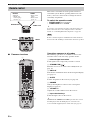
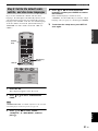
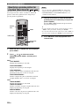
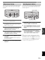
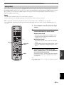
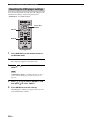
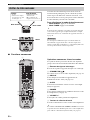
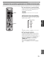
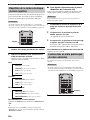
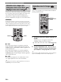
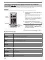
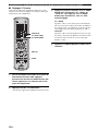
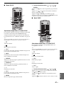
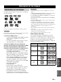
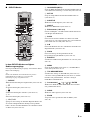
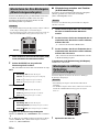
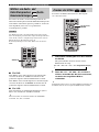
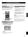
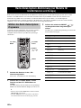
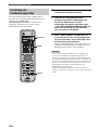
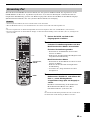
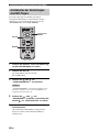
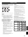
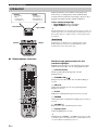
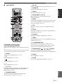
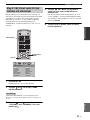
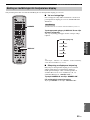
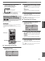
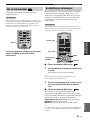
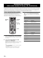
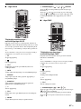
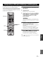
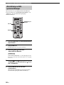
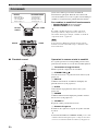
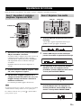
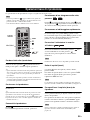
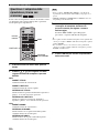
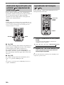
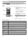
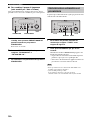
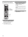
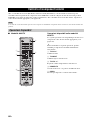
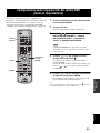
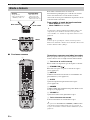
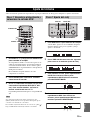
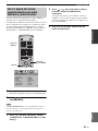
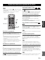
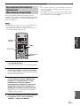
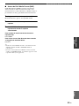
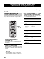
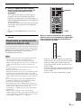
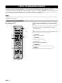
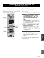
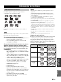
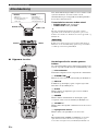
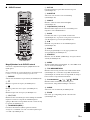
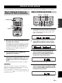
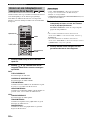
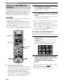
■ Common functions
This remote control has two main operation modes to
control this system. Before operating functions in each
mode, you need to select a mode to change the remote
control key assignments.
To switch the operation mode
• DVD/CD mode: Press DVD/CD.
• TUNER mode: Press TUNER.
y
You can also operate the TV and other components (such as an
iPod) connected to the receiver using the remote control. For
details, see “Controlling External Components” on page 46.
Remote control descriptions and illustrations in this manual are
based on the U.K. and Europe models unless otherwise specified.
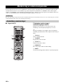
Operations common to all modes
The following operations are available for the receiver
when the remote control is in any operation modes.
1 Infrared signal transmitter
Sends signals to the component you want to control.
2 STANDBY/ON ( )
Turns the receiver on or sets it to the standby mode (see
page 19).
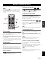
3 DISPLAY
Switches the information shown in the front panel display
(see page 23).
4 SLEEP
Sets the sleep timer on the receiver (see page 44).
5 DIMMER
Changes the brightness of the receiver’s front panel
display (see page 23).
6 VOLUME +/–
Adjusts the overall volume level on the receiver.
7 Input selection keys
Select the input source on the receiver.
y
STANDBY/ON, DIMMER and SLEEP operations also control
the DVD player when the DVD player is connected to the
receiver with the supplied system control cable (see page 12).
Remote control
STANDBY/ON
POWER
TV
1234
56
90
78
SCAN
DIMMER
SLEEP
DVD/CD TUNER BAND
TAPE/MD
SUBTITLE ANGLE ZOOM AUDIO
AUX/TV
DOCK
DVD/CD
• Playback
• Subtitle and
audio language
selection, etc.
TUNER
• Radio station
tuning
• Radio station
preset, etc.
DVD/CD mode
TUNER mode
TUNER
DVD/CD
STANDBY/ON
POWER
TV
1234
56
90
78
SCAN DIMMER
A-B
PROG
SHUFFLETV INPUT
ON SCREEN MENU
PRESET
ENTER
A-E
DISPLAY
SLEEP
DVD/CD TUNER BAND
TAPE/MD
SUBTITLE ANGLE ZOOM AUDIO
AUX/TV DOCK
A-E
INFO.
SET UP
TV VOL VOLUME
TOP MENU
/RETURN
TV CH
REPEAT
1
2
3
4
5
6
7
FREQ/TEXT
PTY SEEK
MODE START
Note

9 En
Controls and Functions
English
INTRODUCTION
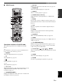
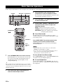
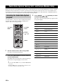
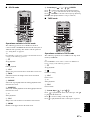
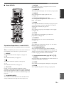
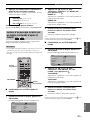
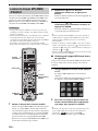
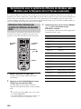
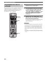
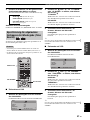
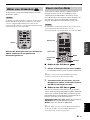
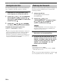
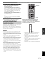
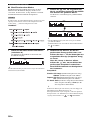
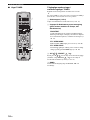
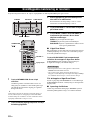
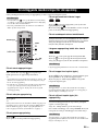
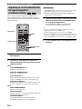
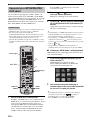
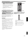
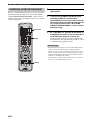
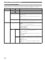
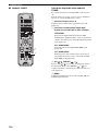
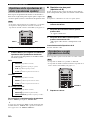
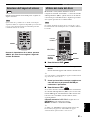
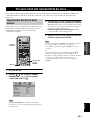
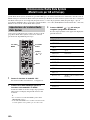
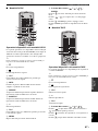
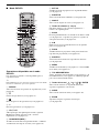
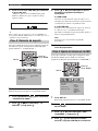
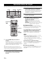
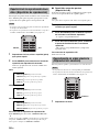
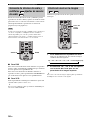
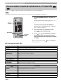
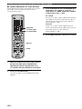
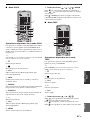
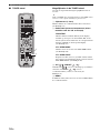
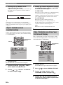
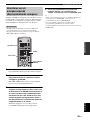
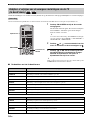
■ DVD/CD mode
Operations available in DVD/CD mode
The following operations are available for the DVD
player.
y
Press DVD/CD to set the remote control to the DVD/CD mode
before carrying out the following operations.
1 REPEAT
Selects the Repeat Play mode (see page 26).
2 s
Stops playback (see page 25).
3 e
Pauses playback (see page 25).
4 h
Starts playback (see page 25).
5 b, a
Skips to the beginning of the current chapter/track or next
chapter/track. Press and hold to fast reverse or fast
forward (see page 25).
6 ON SCREEN (INFO.)
Displays the OSD menu on the TV screen or switches the
time display of CDs (see page 34).
7 SET UP
Displays the setup menu on the TV screen (see page 51).
8 SUBTITLE
Selects the subtitle language (see page 30).
9 ANGLE
Selects a viewing angle (see page 31).
0 Number keys (1 to 9, 0)
Input numerals to specify parameters or chapter/track
numbers.
A SCAN
Previews the content of a DVD or VCD (see page 28) or
plays back the first few seconds of each track on a CD (see
page 25).
B A-B
Repeats a specified section within a chapter/track (see
page 26).
C PROG
Displays the program list used for the Program Play
feature (see page 29).
D SHUFFLE
Turns on/off the Shuffle Play feature (see page 26).
E MENU
Displays the DVD menu (see page 31) or PBC menu of a
VCD (see page 31).
F TOP MENU/RETURN
Returns to the top of the DVD menu (see page 31) or to
the previous PBC menu (see page 31). Press and hold to
return to the previous DVD menu.
G Cursor keys ( / / / ), ENTER
Selects an item in the menu screen or specify the selected
parameter.
H AUDIO
Selects the audio language (see page 30).
I ZOOM
Zooms in a specified part of picture (see page 30).
STANDBY/ON
POWER
TV
1234
56
90
78
SCAN DIMMER
A-B
PROG
SHUFFLETV INPUT
ON SCREEN MENU
PRESET
ENTER
A-E
DISPLAY
SLEEP
DVD/CD TUNER BAND
TAPE/MD
SUBTITLE ANGLE ZOOM AUDIO
AUX/TV DOCK
A-E
INFO.
SET UP
TV VOL VOLUME
TOP MENU
/RETURN
TV CH
REPEAT
FREQ/TEXT
PTY SEEK
MODE START
0
A
B
C
D
E
F
G
H
I
1
2
3
4
5
6
7
8
9

10 En
Controls and Functions
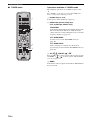
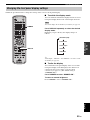
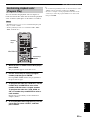
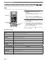
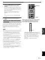
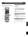
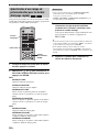
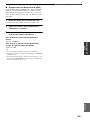
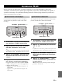
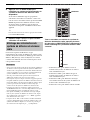
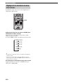
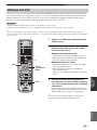
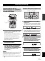
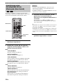
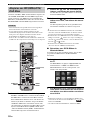
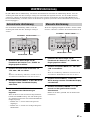
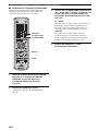
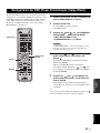
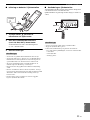
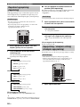
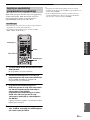
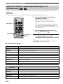
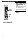
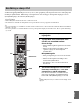
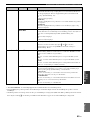
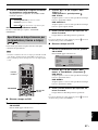
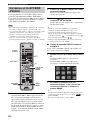
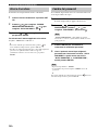
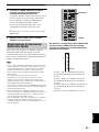
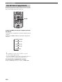
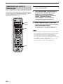
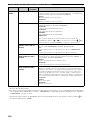
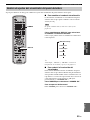
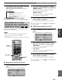
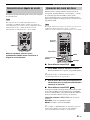
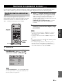
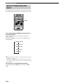
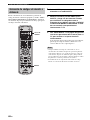
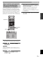
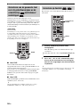
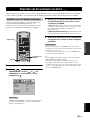
■ TUNER mode Operations available in TUNER mode
The following operations are available for the receiver.
y
Press TUNER to set the remote contol to the TUNER mode
before carrying out the following operations.
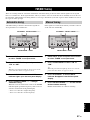
1 Number keys (1 to 8)
Selects preset station number (see page 39).
2 Radio Data System tuning keys
(U.K. and Europe models only)
FREQ/TEXT
Switches the Radio Data System display between the
PS mode, PTY mode, RT mode, CT mode (if the
station offers the corresponding data services) and the
frequency display (see page 41).
PTY SEEK MODE
Sets the receiver to the PTY SEEK mode (see
page 40).
PTY SEEK START
Starts searching for a station once the desired
program type is selected in the PTY SEEK mode (see
page 40).
3 A-E / , PRESET /
Press A-E / to select a preset station group (A to E)
and PRESET / to select a preset station number
(1 to 8) (see page 39).
4 BAND
Switches the radio reception mode between FM, AM and
the preset mode.
STANDBY/ON
POWER
TV
1234
56
90
78
SCAN DIMMER
A-B
PROG
SHUFFLETV INPUT
ON SCREEN MENU
PRESET
ENTER
A-E
DISPLAY
SLEEP
DVD/CD TUNER BAND
TAPE/MD
SUBTITLE ANGLE ZOOM AUDIO
AUX/TV DOCK
A-E
INFO.
SET UP
TV VOL VOLUME
TOP MENU
/RETURN
TV CH
REPEAT
1
2
3
FREQ/TEXT
PTY SEEK
MODE START
4

11 En
Controls and Functions
English
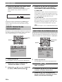
INTRODUCTION
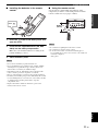
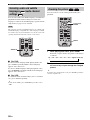
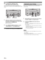
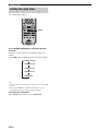
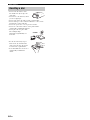
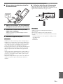
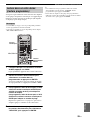
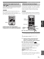
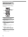
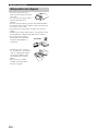
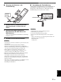
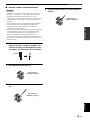
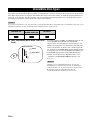
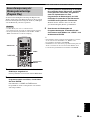
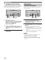
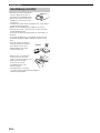
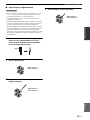
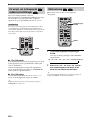
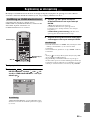
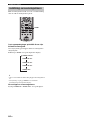
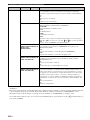
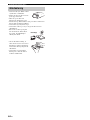
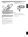
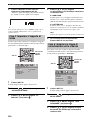
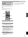
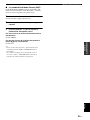
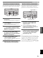
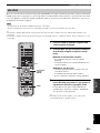
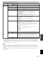
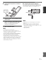
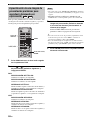
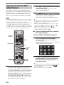
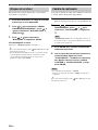
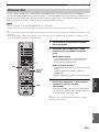
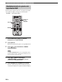
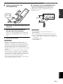
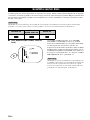
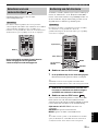
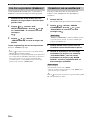
■ Installing the batteries in the remote
control
1 Press the mark on the battery cover and
open the cover.
2 Insert the two supplied batteries (AA, R06,
UM-3) into the battery compartment.
Make sure you insert the batteries according to the
polarity markings (+ and –).
3 Close the battery cover.
• Do not use an old battery together with new one.
• Do not use different types of batteries (for example, alkaline
and manganese) together. Each type of battery has its own
characteristics even if they are similar in shape.
• If the batteries run out, immediately remove them from the
remote control to prevent an explosion or acid leak.
• Dispose of the batteries according to the regional regulations.
• If a battery starts leaking, dispose of it immediately. Be careful
not to let leaking battery acid come into contact with your skin
or clothing. Before inserting new batteries, wipe the
compartment clean.
• Replace the batteries within two minutes to preserve the
memory in the remote control.
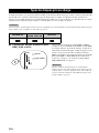
■ Using the remote control
Use the remote control within 6 m (20 feet) of the
component you want to control and point it toward its
remote control sensor (see pages 3 and 6).
• Be careful not to spill liquid on the remote control.
• Be careful not to drop the remote control.
• Do not leave the remote control in the following places:
– hot or humid places, such as near a heater or in a bathroom
– extremely cold places
– dusty places
Notes
Press
Notes
MIN MAX
VOLUME
INPUT
BALANCE
LR
TREBLEBASS
PHONES
STANDBY/ON
TIMER
DISPLAY MEMORY
NATURAL SOUND STEREO RECEIVER RX-E810
PRESET/BAND
PRESET/TUNING
PURE DIRECT
HOURTIMER
TIME ADJ
MIN
AUTO/MAN'L
30˚ 30˚
Within 6 m
(20 feet)

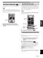
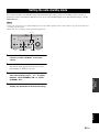
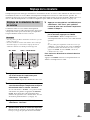
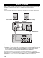
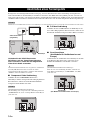
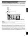
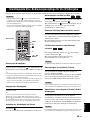
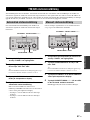
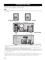
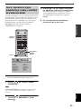
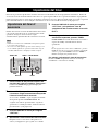
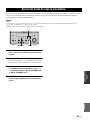
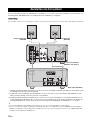
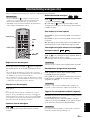
CONNECTING THE SYSTEM
12 En
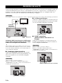
Make sure you read the following procedure and notes carefully before connecting the system. For information on the
speakers (NX-E800), refer to the owner’s manual supplied with it.
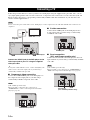
Do not connect the power cable of the receiver, DVD player, or other components to the wall outlet until all cable connections are
completed.
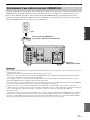
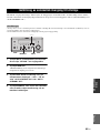
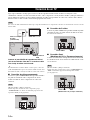
1 Connect the DVD/CD (L/R) jacks of the receiver to the AUDIO OUT (L/R) jacks of the DVD player using the
supplied audio pin cable.
2 Connect the system connector (TO DVD-E810) jack of the receiver to the system connector (TO RX-E810) jack of
the DVD player using the supplied system control cable.
3 Connect the speaker terminals (L) of the receiver to the speaker terminals of the left speaker and the speaker terminals
(R) of the receiver to the speaker terminals of the right speaker using the speaker cables supplied with the speaker set
(NX-E800). See page 13 for details.
y
• The system control connection is used to synchronize the specific operations between the receiver and the DVD player.
• If you want to connect an amplifier with a digital input instead of the RX-E810, use the DIGITAL OUT (COAXIAL or OPTICAL)
jacks of the DVD player and configure the “DIGITAL OUTPUT” setting in the setup menu (see page 52).
Connecting the System
Note
L
R
AV
AUDIO
OUT
DIGITAL OUT
COAXIAL
COMPONENT
S VIDEO VIDEO P
B
P
R
Y
OPTICAL
VIDEO OUT
MAINS
TO RX-E810
LR
LR
MAINS
SPEAKERS
DOCK
DVD/CD
TAPE/MD
AUX
OUT
IN
FM
GND
AM
ANTENNA
75
UNBAL.
TO DVD-E810
SUBWOOFER
OUT
100W MAX. TOTAL
AC OUTLETS
SWITCHED
6
MIN / SPEAKER
1
3
3
2
Receiver (RX-E810)
(Europe model)
DVD player (DVD-E810)
Left speaker
(NX-E800)
Right speaker
(NX-E800)

Connecting the System
13 En
English
PREPARATION
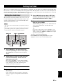
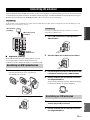
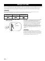
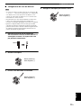
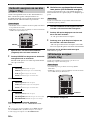
■ Connecting the speaker cable
• Be sure to connect the left channel (L), right channel (R), “+”
(red) and “–” (black) properly. If the connections are faulty, no
sound will be heard from the speakers, and if the polarity of the
speaker connections is incorrect, the sound will be unnatural
and lack bass.
• Do not let the bare speaker wires touch each other or do not let
them touch any metal part of the receiver. This could damage
the receiver and/or the speakers.
• When connecting another speaker set instead of the NX-E800,
be sure to use speakers with the specified impedance shown on
the rear panel of the receiver and magnetically shielded. In case
the magnetically shielded speakers interfere with the monitor,
place the speakers away from the monitor.
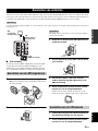
1 Remove approximately 10 mm (3/8 in) of
insulation from the end of each speaker
cable and then twist the exposed wires of the
cable together to prevent short circuits.
2 Unscrew the knob.
3 Insert the bare wire into the terminal.
4 Tighten the knob to secure the wire.
Notes
10 mm (3/8 in)
Red: positive (+)
Black: negative (–)
Red: positive (+)
Black: negative (–)
Red: positive (+)
Black: negative (–)

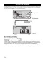
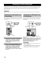
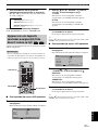
CONNECTING A TV
14 En
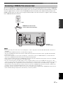
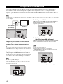
Follow the procedure below to connect your TV to the DVD player using the supplied video pin cable. Also, you can
enjoy high-quality pictures with a S-video connection, a component video connection or a scart connection (U.K. and
Europe models only) using a corresponding commercially available cable. For information on your TV, refer to the
owner’s manual supplied with it.
Do not connect the power cable of the receiver, DVD player, or other components to the wall outlet until all cable connections are
completed.
Connect the VIDEO jack of the DVD player to the
video input jack of your TV using the supplied
video pin cable.
y
To enjoy TV sounds with the receiver, connect AUX (L/R) jacks
of the receiver to the audio output jacks of your TV using a
commercially available audio pin cable.
■ Component video connection
Connect the COMPONENT jacks of the DVD player to
the component video input jacks of your TV using a
commercially available component video cable.
(U.K. and Europe models only)
When you make a component video connection, set
“COMPONENT” to “YUV” in the setup menu of the DVD
player (see page 54).
■ S-video connection
Connect the S VIDEO jack of the DVD player to the
S-video input jack of your TV using a commercially
available S-video cable.
■ Scart connection
(U.K. and Europe models only)
Connect the AV terminal of the DVD player to the scart
input terminal of your TV using a commercially available
scart cable.
(U.K. and Europe models only)
When you make a scart connection, set “COMPONENT” to
“RGB” in the setup menu of the DVD player (see page 54).
Connecting a TV
Note
Note
L
R
AV
AUDI O
OUT
DIGITAL OUT
COAXIAL
COMPONENT
S VIDEO VIDEO P
B
P
R
Y
OPTICAL
VIDEO OUT
MAINS
TO RX-E810
IN
VIDEO
Video pin cable
(supplied)
DVD player
TV
L
R
AV
AUDI O
OUT
DIGITAL OUT
COAXIAL
COMPONENT
S VIDEO VIDEO P
B
P
R
Y
OPTICAL
VIDEO OUT
TO RX-E810
COMPONENT jacks
Note
L
R
AV
AUDIO
OUT
DIGITAL OUT
COAXIAL
COMPONENT
S VIDEO VIDEO P
B
P
R
Y
OPTICAL
VIDEO OUT
TO RX-E810
S VIDEO jack
L
R
AV
AUDIO
OUT
DIGITAL OUT
COAXIAL
COMPONENT
S VIDEO VIDEO P
B
P
R
Y
OPTICAL
VIDEO OUT
TO RX-E810
(U.K. and Europe models only)
AV terminal

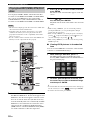
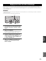
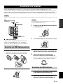
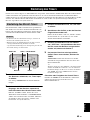
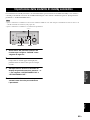
CONNECTING ANTENNAS
15 En
English
PREPARATION
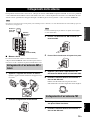
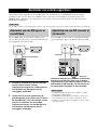
To enjoy radio on the receiver, connect the supplied AM and FM antennas to the designated terminals. If there is a
problem of weak radio wave reception in your area or you want to improve radio reception, we recommend that you use
optional outdoor antennas. For details, consult the nearest authorized YAMAHA dealer or service center.
Be sure to set the tuner frequency step (Asia and Taiwan models only) according to the frequency spacing in your area (see page 38).
■ About grounding
For maximum safety and minimum interference, connect
the antenna GND terminal to a good earth ground. A good
earth ground is a metal stake driven into moist earth.
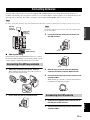
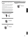
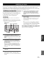
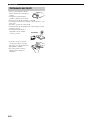
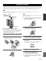
1 Attach the antenna stand to the antenna.
When attaching the antenna to the wall, you do not
need to use the antenna stand.
2 Press down the tab of the AM terminal.
Depending on the product, the shape of the tab is different from
the described illust.
3 Insert the AM loop antenna lead wires into
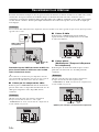
the AM terminal.
4 Replace the tab back to secure the wire.
5 Repeat steps 2 to 4 to insert the AM loop
antenna lead wires into the GND terminal.
6 Place the antenna away from the receiver and
speaker cables.
While listening to the radio, rotate the antenna head
to find the best angle for reception.
1 Connect the supplied indoor FM antenna to
the FM jack of the receiver.
2 Place the antenna away from the receiver and
speaker cables.
Connecting Antennas
Note
Connecting the AM loop antenna
LR
LR
SPEAKERS
DOCK
DVD/CD
TAPE/MD
AUX
OUT
IN
FM
GND
AM
ANTENNA
75
UNBAL.
6
MIN / SPEAKER
Indoor FM
antenna
(supplied)
AM loop
antenna
(supplied)
Ground
(GND terminal)
Note
Connecting the FM antenna

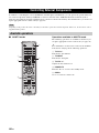
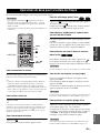
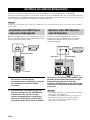
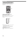
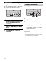
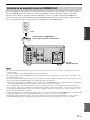
CONNECTING EXTERNAL COMPONENTS
16 En
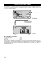
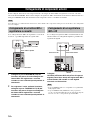
You can connect various audio components, such as an MD player, a tape deck or a YAMAHA iPod universal dock to the
receiver. Also you can connect an MD recorder or a CD recorder to the DVD player using the DIGITAL OUT jacks. For
information on your external component, refer to the owner’s manual supplied with each component.
Do not connect the power cable of the receiver, DVD player, or other components to the wall outlet until all cable connections are
completed.
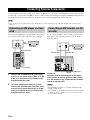
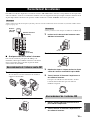
If you connect an MD player or a tape deck to the receiver,
you can enjoy audio sources played on the component.
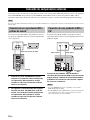
1 Connect the TAPE/MD IN (L/R) jacks of the
receiver to the analog output jacks of an MD
player or a tape deck using a commercially
available audio pin cable.
2 To record audio output from the receiver,
connect the TAPE/MD OUT (L/R) jacks of the
receiver to the analog input jacks of an MD
player or a tape deck using a commercially
available audio pin cable.
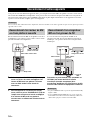
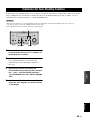
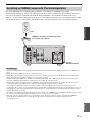
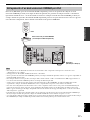
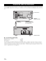
If you connect an MD recorder or a CD recorder to the
DVD player with a digital connection, you can make a
digital recording.
Connect the DIGITAL OUT (COAXIAL or
OPTICAL) jack of the DVD player to the digital
input (coaxial or optical) jack of an MD recorder
or a CD recorder using a commercially available
coaxial or optical cable.
• The DIGITAL OUT jacks are compatible with PCM, Dolby
Digital and DTS signals.
• The DIGITAL OUT (OPTICAL) jack is designed based on EIA
standards. To make a digital connection, use an optical cable
that meets EIA standards.
Connecting External Components
Note
Connecting an MD player or a tape
deck
LR
DOCK
DVD/CD
TAPE/MD
AUX
OUT
IN
FM
GND
AM
ANTENNA
75
UNBAL.
L
R
ANALOG
OUTIN
MD player or
tape deck
Audio pin cable
Receiver
Connecting an MD recorder or a CD
recorder
Notes
L
R
AV
AUDIO
OUT
DIGITAL OUT
COAXIAL
COMPONENT
VIDEO P
B
P
R
Y
OPTICAL
VIDEO OUT
TO RX-E810
COAXIAL OPTICAL
MD recorder or
CD recorder
DVD player
Optical cable
or
Coaxial cable
Pagina se încarcă...
Pagina se încarcă...
Pagina se încarcă...
Pagina se încarcă...
Pagina se încarcă...
Pagina se încarcă...
Pagina se încarcă...
Pagina se încarcă...
Pagina se încarcă...
Pagina se încarcă...
Pagina se încarcă...
Pagina se încarcă...
Pagina se încarcă...
Pagina se încarcă...
Pagina se încarcă...
Pagina se încarcă...
Pagina se încarcă...
Pagina se încarcă...
Pagina se încarcă...
Pagina se încarcă...
Pagina se încarcă...
Pagina se încarcă...
Pagina se încarcă...
Pagina se încarcă...
Pagina se încarcă...
Pagina se încarcă...
Pagina se încarcă...
Pagina se încarcă...
Pagina se încarcă...
Pagina se încarcă...
Pagina se încarcă...
Pagina se încarcă...
Pagina se încarcă...
Pagina se încarcă...
Pagina se încarcă...
Pagina se încarcă...
Pagina se încarcă...
Pagina se încarcă...
Pagina se încarcă...
Pagina se încarcă...
Pagina se încarcă...
Pagina se încarcă...
Pagina se încarcă...
Pagina se încarcă...
Pagina se încarcă...
Pagina se încarcă...
Pagina se încarcă...
Pagina se încarcă...
Pagina se încarcă...
Pagina se încarcă...
Pagina se încarcă...
Pagina se încarcă...
Pagina se încarcă...
Pagina se încarcă...
Pagina se încarcă...
Pagina se încarcă...
Pagina se încarcă...
Pagina se încarcă...
Pagina se încarcă...
Pagina se încarcă...
Pagina se încarcă...
Pagina se încarcă...
Pagina se încarcă...
Pagina se încarcă...
Pagina se încarcă...
Pagina se încarcă...
Pagina se încarcă...
Pagina se încarcă...
Pagina se încarcă...
Pagina se încarcă...
Pagina se încarcă...
Pagina se încarcă...
Pagina se încarcă...
Pagina se încarcă...
Pagina se încarcă...
Pagina se încarcă...
Pagina se încarcă...
Pagina se încarcă...
Pagina se încarcă...
Pagina se încarcă...
Pagina se încarcă...
Pagina se încarcă...
Pagina se încarcă...
Pagina se încarcă...
Pagina se încarcă...
Pagina se încarcă...
Pagina se încarcă...
Pagina se încarcă...
Pagina se încarcă...
Pagina se încarcă...
Pagina se încarcă...
Pagina se încarcă...
Pagina se încarcă...
Pagina se încarcă...
Pagina se încarcă...
Pagina se încarcă...
Pagina se încarcă...
Pagina se încarcă...
Pagina se încarcă...
Pagina se încarcă...
Pagina se încarcă...
Pagina se încarcă...
Pagina se încarcă...
Pagina se încarcă...
Pagina se încarcă...
Pagina se încarcă...
Pagina se încarcă...
Pagina se încarcă...
Pagina se încarcă...
Pagina se încarcă...
Pagina se încarcă...
Pagina se încarcă...
Pagina se încarcă...
Pagina se încarcă...
Pagina se încarcă...
Pagina se încarcă...
Pagina se încarcă...
Pagina se încarcă...
Pagina se încarcă...
Pagina se încarcă...
Pagina se încarcă...
Pagina se încarcă...
Pagina se încarcă...
Pagina se încarcă...
Pagina se încarcă...
Pagina se încarcă...
Pagina se încarcă...
Pagina se încarcă...
Pagina se încarcă...
Pagina se încarcă...
Pagina se încarcă...
Pagina se încarcă...
Pagina se încarcă...
Pagina se încarcă...
Pagina se încarcă...
Pagina se încarcă...
Pagina se încarcă...
Pagina se încarcă...
Pagina se încarcă...
Pagina se încarcă...
Pagina se încarcă...
Pagina se încarcă...
Pagina se încarcă...
Pagina se încarcă...
Pagina se încarcă...
Pagina se încarcă...
Pagina se încarcă...
Pagina se încarcă...
Pagina se încarcă...
Pagina se încarcă...
Pagina se încarcă...
Pagina se încarcă...
Pagina se încarcă...
Pagina se încarcă...
Pagina se încarcă...
Pagina se încarcă...
Pagina se încarcă...
Pagina se încarcă...
Pagina se încarcă...
Pagina se încarcă...
Pagina se încarcă...
Pagina se încarcă...
Pagina se încarcă...
Pagina se încarcă...
Pagina se încarcă...
Pagina se încarcă...
Pagina se încarcă...
Pagina se încarcă...
Pagina se încarcă...
Pagina se încarcă...
Pagina se încarcă...
Pagina se încarcă...
Pagina se încarcă...
Pagina se încarcă...
Pagina se încarcă...
Pagina se încarcă...
Pagina se încarcă...
Pagina se încarcă...
Pagina se încarcă...
Pagina se încarcă...
Pagina se încarcă...
Pagina se încarcă...
Pagina se încarcă...
Pagina se încarcă...
Pagina se încarcă...
Pagina se încarcă...
Pagina se încarcă...
Pagina se încarcă...
Pagina se încarcă...
Pagina se încarcă...
Pagina se încarcă...
Pagina se încarcă...
Pagina se încarcă...
Pagina se încarcă...
Pagina se încarcă...
Pagina se încarcă...
Pagina se încarcă...
Pagina se încarcă...
Pagina se încarcă...
Pagina se încarcă...
Pagina se încarcă...
Pagina se încarcă...
Pagina se încarcă...
Pagina se încarcă...
Pagina se încarcă...
Pagina se încarcă...
Pagina se încarcă...
Pagina se încarcă...
Pagina se încarcă...
Pagina se încarcă...
Pagina se încarcă...
Pagina se încarcă...
Pagina se încarcă...
Pagina se încarcă...
Pagina se încarcă...
Pagina se încarcă...
Pagina se încarcă...
Pagina se încarcă...
Pagina se încarcă...
Pagina se încarcă...
Pagina se încarcă...
Pagina se încarcă...
Pagina se încarcă...
Pagina se încarcă...
Pagina se încarcă...
Pagina se încarcă...
Pagina se încarcă...
Pagina se încarcă...
Pagina se încarcă...
Pagina se încarcă...
Pagina se încarcă...
Pagina se încarcă...
Pagina se încarcă...
Pagina se încarcă...
Pagina se încarcă...
Pagina se încarcă...
Pagina se încarcă...
Pagina se încarcă...
Pagina se încarcă...
Pagina se încarcă...
Pagina se încarcă...
Pagina se încarcă...
Pagina se încarcă...
Pagina se încarcă...
Pagina se încarcă...
Pagina se încarcă...
Pagina se încarcă...
Pagina se încarcă...
Pagina se încarcă...
Pagina se încarcă...
Pagina se încarcă...
Pagina se încarcă...
Pagina se încarcă...
Pagina se încarcă...
Pagina se încarcă...
Pagina se încarcă...
Pagina se încarcă...
Pagina se încarcă...
Pagina se încarcă...
Pagina se încarcă...
Pagina se încarcă...
Pagina se încarcă...
Pagina se încarcă...
Pagina se încarcă...
Pagina se încarcă...
Pagina se încarcă...
Pagina se încarcă...
Pagina se încarcă...
Pagina se încarcă...
Pagina se încarcă...
Pagina se încarcă...
Pagina se încarcă...
Pagina se încarcă...
Pagina se încarcă...
Pagina se încarcă...
Pagina se încarcă...
Pagina se încarcă...
Pagina se încarcă...
Pagina se încarcă...
Pagina se încarcă...
Pagina se încarcă...
Pagina se încarcă...
Pagina se încarcă...
Pagina se încarcă...
Pagina se încarcă...
Pagina se încarcă...
Pagina se încarcă...
Pagina se încarcă...
Pagina se încarcă...
Pagina se încarcă...
Pagina se încarcă...
Pagina se încarcă...
Pagina se încarcă...
Pagina se încarcă...
Pagina se încarcă...
Pagina se încarcă...
Pagina se încarcă...
Pagina se încarcă...
Pagina se încarcă...
Pagina se încarcă...
Pagina se încarcă...
Pagina se încarcă...
Pagina se încarcă...
Pagina se încarcă...
Pagina se încarcă...
Pagina se încarcă...
Pagina se încarcă...
Pagina se încarcă...
Pagina se încarcă...
Pagina se încarcă...
Pagina se încarcă...
Pagina se încarcă...
Pagina se încarcă...
Pagina se încarcă...
Pagina se încarcă...
Pagina se încarcă...
Pagina se încarcă...
Pagina se încarcă...
Pagina se încarcă...
Pagina se încarcă...
Pagina se încarcă...
Pagina se încarcă...
Pagina se încarcă...
Pagina se încarcă...
Pagina se încarcă...
Pagina se încarcă...
Pagina se încarcă...
Pagina se încarcă...
Pagina se încarcă...
Pagina se încarcă...
Pagina se încarcă...
Pagina se încarcă...
Pagina se încarcă...
Pagina se încarcă...
Pagina se încarcă...
Pagina se încarcă...
Pagina se încarcă...
Pagina se încarcă...
Pagina se încarcă...
Pagina se încarcă...
Pagina se încarcă...
Pagina se încarcă...
Pagina se încarcă...
Pagina se încarcă...
Pagina se încarcă...
Pagina se încarcă...
Pagina se încarcă...
Pagina se încarcă...
Pagina se încarcă...
Pagina se încarcă...
Pagina se încarcă...
Pagina se încarcă...
Pagina se încarcă...
Pagina se încarcă...
Pagina se încarcă...
Pagina se încarcă...
Pagina se încarcă...
Pagina se încarcă...
Pagina se încarcă...
Pagina se încarcă...
Pagina se încarcă...
Pagina se încarcă...
Pagina se încarcă...
Pagina se încarcă...
Pagina se încarcă...
Pagina se încarcă...
Pagina se încarcă...
Pagina se încarcă...
Pagina se încarcă...
Pagina se încarcă...
Pagina se încarcă...
Pagina se încarcă...
Pagina se încarcă...
Pagina se încarcă...
Pagina se încarcă...
Pagina se încarcă...
Pagina se încarcă...
Pagina se încarcă...
Pagina se încarcă...
Pagina se încarcă...
Pagina se încarcă...
Pagina se încarcă...
Pagina se încarcă...
Pagina se încarcă...
Pagina se încarcă...
Pagina se încarcă...
Pagina se încarcă...
Pagina se încarcă...
Pagina se încarcă...
Pagina se încarcă...
Pagina se încarcă...
Pagina se încarcă...
Pagina se încarcă...
Pagina se încarcă...
Pagina se încarcă...
Pagina se încarcă...
Pagina se încarcă...
Pagina se încarcă...
Pagina se încarcă...
Pagina se încarcă...
Pagina se încarcă...
Pagina se încarcă...
Pagina se încarcă...
Pagina se încarcă...
Pagina se încarcă...
Pagina se încarcă...
Pagina se încarcă...
Pagina se încarcă...
Pagina se încarcă...
Pagina se încarcă...
Pagina se încarcă...
Pagina se încarcă...
Pagina se încarcă...
Pagina se încarcă...
Pagina se încarcă...
Pagina se încarcă...
Pagina se încarcă...
Pagina se încarcă...
Pagina se încarcă...
Pagina se încarcă...
Pagina se încarcă...
Pagina se încarcă...
Pagina se încarcă...
Pagina se încarcă...
Pagina se încarcă...
Pagina se încarcă...
Pagina se încarcă...
Pagina se încarcă...
Pagina se încarcă...
Pagina se încarcă...
Pagina se încarcă...
Pagina se încarcă...
Pagina se încarcă...
Pagina se încarcă...
Pagina se încarcă...
Pagina se încarcă...
Pagina se încarcă...
Pagina se încarcă...
Pagina se încarcă...
Pagina se încarcă...
Pagina se încarcă...
Pagina se încarcă...
Pagina se încarcă...
Pagina se încarcă...
Pagina se încarcă...
Pagina se încarcă...
Pagina se încarcă...
Pagina se încarcă...
Pagina se încarcă...
Pagina se încarcă...
Pagina se încarcă...
Pagina se încarcă...
Pagina se încarcă...
Pagina se încarcă...
Pagina se încarcă...
Pagina se încarcă...
Pagina se încarcă...
Pagina se încarcă...
Pagina se încarcă...
Pagina se încarcă...
Pagina se încarcă...
Pagina se încarcă...
Pagina se încarcă...
Pagina se încarcă...
Pagina se încarcă...
Pagina se încarcă...
Pagina se încarcă...
Pagina se încarcă...
Pagina se încarcă...
Pagina se încarcă...
Pagina se încarcă...
Pagina se încarcă...
Pagina se încarcă...
Pagina se încarcă...
Pagina se încarcă...
Pagina se încarcă...
Pagina se încarcă...
Pagina se încarcă...
Pagina se încarcă...
Pagina se încarcă...
Pagina se încarcă...
Pagina se încarcă...
Pagina se încarcă...
Pagina se încarcă...
Pagina se încarcă...
Pagina se încarcă...
Pagina se încarcă...
Pagina se încarcă...
Pagina se încarcă...
Pagina se încarcă...
Pagina se încarcă...
Pagina se încarcă...
Pagina se încarcă...
Pagina se încarcă...
Pagina se încarcă...
Pagina se încarcă...
Pagina se încarcă...
Pagina se încarcă...
Pagina se încarcă...
Pagina se încarcă...
Pagina se încarcă...
Pagina se încarcă...
Pagina se încarcă...
Pagina se încarcă...
Pagina se încarcă...
Pagina se încarcă...
Pagina se încarcă...
Pagina se încarcă...
Pagina se încarcă...
Pagina se încarcă...
Pagina se încarcă...
Pagina se încarcă...
Pagina se încarcă...
Pagina se încarcă...
Pagina se încarcă...
Pagina se încarcă...
Pagina se încarcă...
Pagina se încarcă...
Pagina se încarcă...
Pagina se încarcă...
Pagina se încarcă...
Pagina se încarcă...
Pagina se încarcă...
Pagina se încarcă...
Pagina se încarcă...
Pagina se încarcă...
Pagina se încarcă...
Pagina se încarcă...
-
 1
1
-
 2
2
-
 3
3
-
 4
4
-
 5
5
-
 6
6
-
 7
7
-
 8
8
-
 9
9
-
 10
10
-
 11
11
-
 12
12
-
 13
13
-
 14
14
-
 15
15
-
 16
16
-
 17
17
-
 18
18
-
 19
19
-
 20
20
-
 21
21
-
 22
22
-
 23
23
-
 24
24
-
 25
25
-
 26
26
-
 27
27
-
 28
28
-
 29
29
-
 30
30
-
 31
31
-
 32
32
-
 33
33
-
 34
34
-
 35
35
-
 36
36
-
 37
37
-
 38
38
-
 39
39
-
 40
40
-
 41
41
-
 42
42
-
 43
43
-
 44
44
-
 45
45
-
 46
46
-
 47
47
-
 48
48
-
 49
49
-
 50
50
-
 51
51
-
 52
52
-
 53
53
-
 54
54
-
 55
55
-
 56
56
-
 57
57
-
 58
58
-
 59
59
-
 60
60
-
 61
61
-
 62
62
-
 63
63
-
 64
64
-
 65
65
-
 66
66
-
 67
67
-
 68
68
-
 69
69
-
 70
70
-
 71
71
-
 72
72
-
 73
73
-
 74
74
-
 75
75
-
 76
76
-
 77
77
-
 78
78
-
 79
79
-
 80
80
-
 81
81
-
 82
82
-
 83
83
-
 84
84
-
 85
85
-
 86
86
-
 87
87
-
 88
88
-
 89
89
-
 90
90
-
 91
91
-
 92
92
-
 93
93
-
 94
94
-
 95
95
-
 96
96
-
 97
97
-
 98
98
-
 99
99
-
 100
100
-
 101
101
-
 102
102
-
 103
103
-
 104
104
-
 105
105
-
 106
106
-
 107
107
-
 108
108
-
 109
109
-
 110
110
-
 111
111
-
 112
112
-
 113
113
-
 114
114
-
 115
115
-
 116
116
-
 117
117
-
 118
118
-
 119
119
-
 120
120
-
 121
121
-
 122
122
-
 123
123
-
 124
124
-
 125
125
-
 126
126
-
 127
127
-
 128
128
-
 129
129
-
 130
130
-
 131
131
-
 132
132
-
 133
133
-
 134
134
-
 135
135
-
 136
136
-
 137
137
-
 138
138
-
 139
139
-
 140
140
-
 141
141
-
 142
142
-
 143
143
-
 144
144
-
 145
145
-
 146
146
-
 147
147
-
 148
148
-
 149
149
-
 150
150
-
 151
151
-
 152
152
-
 153
153
-
 154
154
-
 155
155
-
 156
156
-
 157
157
-
 158
158
-
 159
159
-
 160
160
-
 161
161
-
 162
162
-
 163
163
-
 164
164
-
 165
165
-
 166
166
-
 167
167
-
 168
168
-
 169
169
-
 170
170
-
 171
171
-
 172
172
-
 173
173
-
 174
174
-
 175
175
-
 176
176
-
 177
177
-
 178
178
-
 179
179
-
 180
180
-
 181
181
-
 182
182
-
 183
183
-
 184
184
-
 185
185
-
 186
186
-
 187
187
-
 188
188
-
 189
189
-
 190
190
-
 191
191
-
 192
192
-
 193
193
-
 194
194
-
 195
195
-
 196
196
-
 197
197
-
 198
198
-
 199
199
-
 200
200
-
 201
201
-
 202
202
-
 203
203
-
 204
204
-
 205
205
-
 206
206
-
 207
207
-
 208
208
-
 209
209
-
 210
210
-
 211
211
-
 212
212
-
 213
213
-
 214
214
-
 215
215
-
 216
216
-
 217
217
-
 218
218
-
 219
219
-
 220
220
-
 221
221
-
 222
222
-
 223
223
-
 224
224
-
 225
225
-
 226
226
-
 227
227
-
 228
228
-
 229
229
-
 230
230
-
 231
231
-
 232
232
-
 233
233
-
 234
234
-
 235
235
-
 236
236
-
 237
237
-
 238
238
-
 239
239
-
 240
240
-
 241
241
-
 242
242
-
 243
243
-
 244
244
-
 245
245
-
 246
246
-
 247
247
-
 248
248
-
 249
249
-
 250
250
-
 251
251
-
 252
252
-
 253
253
-
 254
254
-
 255
255
-
 256
256
-
 257
257
-
 258
258
-
 259
259
-
 260
260
-
 261
261
-
 262
262
-
 263
263
-
 264
264
-
 265
265
-
 266
266
-
 267
267
-
 268
268
-
 269
269
-
 270
270
-
 271
271
-
 272
272
-
 273
273
-
 274
274
-
 275
275
-
 276
276
-
 277
277
-
 278
278
-
 279
279
-
 280
280
-
 281
281
-
 282
282
-
 283
283
-
 284
284
-
 285
285
-
 286
286
-
 287
287
-
 288
288
-
 289
289
-
 290
290
-
 291
291
-
 292
292
-
 293
293
-
 294
294
-
 295
295
-
 296
296
-
 297
297
-
 298
298
-
 299
299
-
 300
300
-
 301
301
-
 302
302
-
 303
303
-
 304
304
-
 305
305
-
 306
306
-
 307
307
-
 308
308
-
 309
309
-
 310
310
-
 311
311
-
 312
312
-
 313
313
-
 314
314
-
 315
315
-
 316
316
-
 317
317
-
 318
318
-
 319
319
-
 320
320
-
 321
321
-
 322
322
-
 323
323
-
 324
324
-
 325
325
-
 326
326
-
 327
327
-
 328
328
-
 329
329
-
 330
330
-
 331
331
-
 332
332
-
 333
333
-
 334
334
-
 335
335
-
 336
336
-
 337
337
-
 338
338
-
 339
339
-
 340
340
-
 341
341
-
 342
342
-
 343
343
-
 344
344
-
 345
345
-
 346
346
-
 347
347
-
 348
348
-
 349
349
-
 350
350
-
 351
351
-
 352
352
-
 353
353
-
 354
354
-
 355
355
-
 356
356
-
 357
357
-
 358
358
-
 359
359
-
 360
360
-
 361
361
-
 362
362
-
 363
363
-
 364
364
-
 365
365
-
 366
366
-
 367
367
-
 368
368
-
 369
369
-
 370
370
-
 371
371
-
 372
372
-
 373
373
-
 374
374
-
 375
375
-
 376
376
-
 377
377
-
 378
378
-
 379
379
-
 380
380
-
 381
381
-
 382
382
-
 383
383
-
 384
384
-
 385
385
-
 386
386
-
 387
387
-
 388
388
-
 389
389
-
 390
390
-
 391
391
-
 392
392
-
 393
393
-
 394
394
-
 395
395
-
 396
396
-
 397
397
-
 398
398
-
 399
399
-
 400
400
-
 401
401
-
 402
402
-
 403
403
-
 404
404
-
 405
405
-
 406
406
-
 407
407
-
 408
408
-
 409
409
-
 410
410
-
 411
411
-
 412
412
-
 413
413
-
 414
414
-
 415
415
-
 416
416
-
 417
417
-
 418
418
-
 419
419
-
 420
420
-
 421
421
-
 422
422
-
 423
423
-
 424
424
-
 425
425
-
 426
426
-
 427
427
-
 428
428
-
 429
429
-
 430
430
-
 431
431
-
 432
432
-
 433
433
-
 434
434
-
 435
435
-
 436
436
-
 437
437
-
 438
438
-
 439
439
-
 440
440
-
 441
441
-
 442
442
-
 443
443
-
 444
444
-
 445
445
-
 446
446
-
 447
447
-
 448
448
-
 449
449
-
 450
450
-
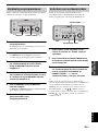 451
451
-
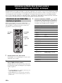 452
452
-
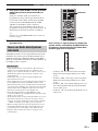 453
453
-
 454
454
-
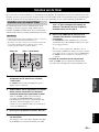 455
455
-
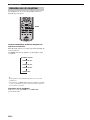 456
456
-
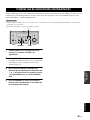 457
457
-
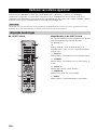 458
458
-
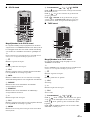 459
459
-
 460
460
-
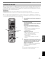 461
461
-
 462
462
-
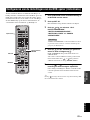 463
463
-
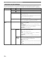 464
464
-
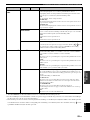 465
465
-
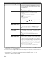 466
466
-
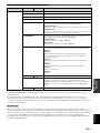 467
467
-
 468
468
-
 469
469
-
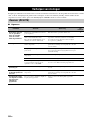 470
470
-
 471
471
-
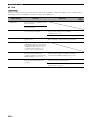 472
472
-
 473
473
-
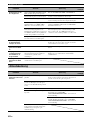 474
474
-
 475
475
-
 476
476
-
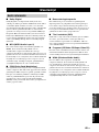 477
477
-
 478
478
-
 479
479
-
 480
480
-
 481
481
-
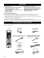 482
482
-
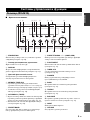 483
483
-
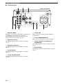 484
484
-
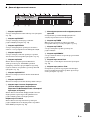 485
485
-
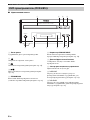 486
486
-
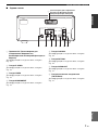 487
487
-
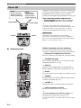 488
488
-
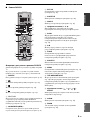 489
489
-
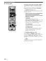 490
490
-
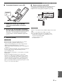 491
491
-
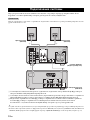 492
492
-
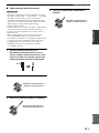 493
493
-
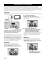 494
494
-
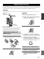 495
495
-
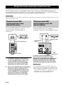 496
496
-
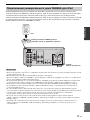 497
497
-
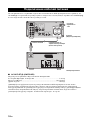 498
498
-
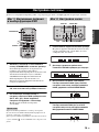 499
499
-
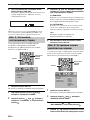 500
500
-
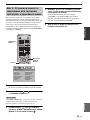 501
501
-
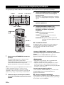 502
502
-
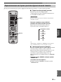 503
503
-
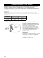 504
504
-
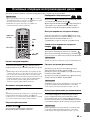 505
505
-
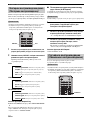 506
506
-
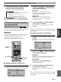 507
507
-
 508
508
-
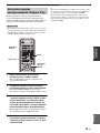 509
509
-
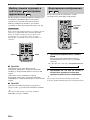 510
510
-
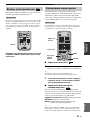 511
511
-
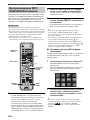 512
512
-
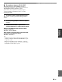 513
513
-
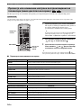 514
514
-
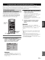 515
515
-
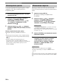 516
516
-
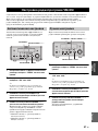 517
517
-
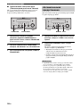 518
518
-
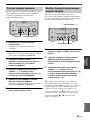 519
519
-
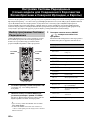 520
520
-
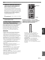 521
521
-
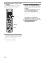 522
522
-
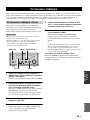 523
523
-
 524
524
-
 525
525
-
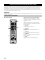 526
526
-
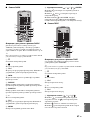 527
527
-
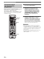 528
528
-
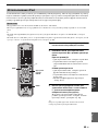 529
529
-
 530
530
-
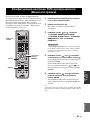 531
531
-
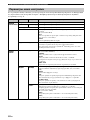 532
532
-
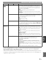 533
533
-
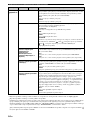 534
534
-
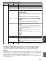 535
535
-
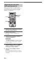 536
536
-
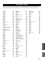 537
537
-
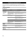 538
538
-
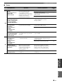 539
539
-
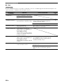 540
540
-
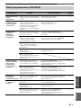 541
541
-
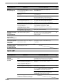 542
542
-
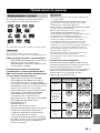 543
543
-
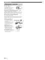 544
544
-
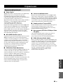 545
545
-
 546
546
-
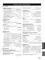 547
547
-
 548
548


Yamaha MCR-E810 Manual de utilizare
- Categorie
- DVD playere
- Tip
- Manual de utilizare
în alte limbi
- Türkçe: Yamaha MCR-E810 Kullanım kılavuzu
- français: Yamaha MCR-E810 Manuel utilisateur
- русский: Yamaha MCR-E810 Руководство пользователя
- English: Yamaha MCR-E810 User manual
- suomi: Yamaha MCR-E810 Ohjekirja
- Deutsch: Yamaha MCR-E810 Benutzerhandbuch
- italiano: Yamaha MCR-E810 Manuale utente
- español: Yamaha MCR-E810 Manual de usuario
- svenska: Yamaha MCR-E810 Användarmanual
- dansk: Yamaha MCR-E810 Brugermanual
- Nederlands: Yamaha MCR-E810 Handleiding
Lucrări înrudite
-
Yamaha DVX-700 Manual de utilizare
-
Yamaha MCR-940 Manualul proprietarului
-
-
Yamaha DVR-S200 Manual de utilizare
-
Yamaha MCR-840 Manualul proprietarului
-
-
-
-
-
Yamaha YSP-3000 Manualul proprietarului
