Asus PRIME H510M-A R2.0 Manual de utilizare

Categorie
Plăci de bază
Tip
Manual de utilizare

Acest manual este potrivit și pentru

Motherboard
PRIME
H510M-A R2.0
ii
E21921
First Edition
April 2023
Copyright © 2023 ASUSTeK COMPUTER INC. All Rights Reserved.
No part of this manual, including the products and software described in it, may be reproduced,
transmitted, transcribed, stored in a retrieval system, or translated into any language in any form or by any
means, except documentation kept by the purchaser for backup purposes, without the express written
permission of ASUSTeK COMPUTER INC. (“ASUS”).
Product warranty or service will not be extended if: (1) the product is repaired, modied or altered, unless
such repair, modication of alteration is authorized in writing by ASUS; or (2) the serial number of the
product is defaced or missing.
ASUS PROVIDES THIS MANUAL “AS IS” WITHOUT WARRANTY OF ANY KIND, EITHER EXPRESS
OR IMPLIED, INCLUDING BUT NOT LIMITED TO THE IMPLIED WARRANTIES OR CONDITIONS OF
MERCHANTABILITY OR FITNESS FOR A PARTICULAR PURPOSE. IN NO EVENT SHALL ASUS, ITS
DIRECTORS, OFFICERS, EMPLOYEES OR AGENTS BE LIABLE FOR ANY INDIRECT, SPECIAL,
INCIDENTAL, OR CONSEQUENTIAL DAMAGES (INCLUDING DAMAGES FOR LOSS OF PROFITS,
LOSS OF BUSINESS, LOSS OF USE OR DATA, INTERRUPTION OF BUSINESS AND THE LIKE),
EVEN IF ASUS HAS BEEN ADVISED OF THE POSSIBILITY OF SUCH DAMAGES ARISING FROM ANY
DEFECT OR ERROR IN THIS MANUAL OR PRODUCT.
SPECIFICATIONS AND INFORMATION CONTAINED IN THIS MANUAL ARE FURNISHED FOR
INFORMATIONAL USE ONLY, AND ARE SUBJECT TO CHANGE AT ANY TIME WITHOUT NOTICE,
AND SHOULD NOT BE CONSTRUED AS A COMMITMENT BY ASUS. ASUS ASSUMES NO
RESPONSIBILITY OR LIABILITY FOR ANY ERRORS OR INACCURACIES THAT MAY APPEAR IN THIS
MANUAL, INCLUDING THE PRODUCTS AND SOFTWARE DESCRIBED IN IT.
Products and corporate names appearing in this manual may or may not be registered trademarks or
copyrights of their respective companies, and are used only for identication or explanation and to the
owners’ benet, without intent to infringe.
iii
Contents
Safety information ...................................................................................................... iv
About this guide .......................................................................................................... v
Package contents ....................................................................................................... vi
PRIME H510M-A R2.0 specications summary ....................................................... vi
Chapter 1: Product Introduction
1.1 Before you proceed ...................................................................................... 1-1
1.2 Motherboard overview ................................................................................. 1-2
1.3 Central Processing Unit (CPU) .................................................................... 1-9
1.4 System memory .......................................................................................... 1-10
1.5 M.2 installation ............................................................................................ 1-12
Chapter 2: BIOS Information
2.1 Knowing BIOS ............................................................................................... 2-1
2.2 BIOS Setup program .................................................................................... 2-2
2.3 ASUS EZ Flash 3 ........................................................................................... 2-3
2.4 ASUS CrashFree BIOS 3 .............................................................................. 2-4
Appendix
Notices ..................................................................................................................... A-1
Warranty ................................................................................................................... A-6
ASUS contact information ...................................................................................... A-8
Service and Support ............................................................................................... A-8
iv
Button/Coin Batteries Safety Information
WARNING
KEEP OUT OF REACH OF CHILDREN
Swallowing can lead to chemical burns,
perforation of soft tissue, and death. Severe
burns can occur within 2 hours of ingestion.
Seek medical attention immediately.
Safety information
Electrical safety
To prevent electrical shock hazard, disconnect the power cable from the electrical outlet
before relocating the system.
When adding or removing devices to or from the system, ensure that the power cables
for the devices are unplugged before the signal cables are connected. If possible,
disconnect all power cables from the existing system before you add a device.
Before connecting or removing signal cables from the motherboard, ensure that all power
cables are unplugged.
Seek professional assistance before using an adapter or extension cord. These devices
could interrupt the grounding circuit.
Ensure that your power supply is set to the correct voltage in your area. If you are not
sure about the voltage of the electrical outlet you are using, contact your local power
company.
If the power supply is broken, do not try to x it by yourself. Contact a qualied service
technician or your retailer.
Operation safety
Before installing the motherboard and adding components, carefully read all the manuals
that came with the package.
Before using the product, ensure all cables are correctly connected and the power cables
are not damaged. If you detect any damage, contact your dealer immediately.
To avoid short circuits, keep paper clips, screws, and staples away from connectors,
slots, sockets and circuitry.
Avoid dust, humidity, and temperature extremes. Do not place the product in any area
where it may become wet.
Place the product on a stable surface.
If you encounter technical problems with the product, contact a qualied service
technician or your retailer.
Your motherboard should only be used in environments with ambient temperatures
between 0°C and 40°C.
v
About this guide
This user guide contains the information you need when installing and conguring the
motherboard.
How this guide is organized
This guide contains the following parts:
Chapter 1: Product Introduction
This chapter describes the features of the motherboard and the new technology it
supports. It includes descriptions of the switches, jumpers, and connectors on the
motherboard.
Chapter 2: BIOS Information
This chapter tells how to boot into the BIOS, upgrade BIOS using the EZ Flash Utility.
Where to nd more information
Refer to the following sources for additional information and for product and software
updates.
1. ASUS website
The ASUS website (www.asus.com) provides updated information on ASUS hardware
and software products.
2. Optional documentation
Your product package may include optional documentation, such as warranty flyers,
that may have been added by your dealer. These documents are not part of the
standard package.
Conventions used in this guide
To ensure that you perform certain tasks properly, take note of the following symbols used
throughout this manual.
CAUTION: Information to prevent damage to the components and injuries to yourself when
trying to complete a task.
IMPORTANT: Instructions that you MUST follow to complete a task.
NOTE: Tips and additional information to help you complete a task.
vi
PRIME H510M-A R2.0 specications summary
CPU
Intel® Socket LGA1200 for 11th Gen Intel® Core™ & 10th Gen Intel® Core™,
Pentium® Gold and Celeron® Processors*
Supports Intel® 14 nm CPU
Supports Intel® Turbo Boost Technology 2.0 and Intel® Turbo Boost Max
Technology 3.0**
* Refer to www.asus.com for CPU support list.
** Intel® Turbo Boost Max Technology 3.0 support depends on the CPU types.
Chipset Intel® H470 Chipset
Memory
2 x DIMM slots, Max. 64GB DDR4 Non-ECC, Un-buffered Memory*
Dual Channel Memory Architecture
Supports Intel® Extreme Memory Prole (XMP)
* Supported memory types, data rate (speed), and number of DRAM modules vary
depending on the CPU and memory conguration, for more information please refer
to CPU/Memory Support list under the Support tab of product information site or
visit https://www.asus.com/support/.
Graphics
1 x DisplayPort**
1 x VGA port
1 x HDMI™ port***
*
Graphics specications may vary between CPU types.
** Intel
®
11
th
& 10
th
Gen processors support DisplayPort 1.4 with max. resolution of
4096 x 2304 @60Hz. Please refer to www.intel.com for any updates.
*** Only Intel
®
11
th
Gen processors support HDMI™ 2.1 with max. resolution of
4K@60Hz, others will only support HDMI™ 1.4 with max. resolution of 4K@30Hz.
Please refer to www.intel.com for any updates.
Expansion Slots
Intel® 11th & 10th Gen Processors
1 x PCIe 4.0/3.0 x16 slot
- Intel® 11th Gen processors support PCIe 4.0 x16
- Intel® 10th Gen processors support PCIe 3.0 x16
Intel® H470 Chipset
2 x PCIe 3.0 x1 slots
(continued on the next page)
Package contents
Check your motherboard package for the following items.
Motherboard 1 x PRIME H510M-A R2.0 motherboard
Cables 2 x SATA 6Gb/s cables
Miscellaneous
1 x I/O Shield
1 x M.2 Rubber Package
1 x Screw package for M.2 SSD
Documentation 1 x User guide
If any of the above items is damaged or missing, contact your retailer.
vii
PRIME H510M-A R2.0 specications summary
Storage
Total supports 1 x M.2 slot and 4 x SATA 6Gb/s ports
Intel® H470 Chipset
M.2 slot (Key M), type 2242/2260/2280 (supports PCIe 3.0 x4 & SATA modes)
4 x SATA 6Gb/s ports
Ethernet 1 x Realtek 1Gb Ethernet
USB
Rear USB (Total 6 ports)
4 x USB 3.2 Gen 1 (5G) ports (4 x Type-A)
2 x USB 2.0 ports (2 x Type-A)
Front USB (Total 7 ports)
1 x USB 3.2 Gen 1 (5G) header supports 2 additional USB 3.2 Gen 1 ports
2 x USB 2.0 headers support 4 additional USB 2.0 ports
1 x USB 2.0 header supports 1 additional USB 2.0 port
Audio
Realtek 7.1 Surround Sound High Denition Audio CODEC*
- Supports: Jack-detection, Multi-streaming, Front Panel Jack-retasking
- Supports up to 24-Bit/192kHz playback
Audio Features
- Audio Shielding
- Premium audio capacitors
- Dedicated audio PCB layers
* A chassis with an HD audio module in the front panel is required to support 7.1
Surround Sound audio output.
Back Panel I/O
Ports
4 x USB 3.2 Gen 1 (5G) ports (4 x Type-A)
2 x USB 2.0 ports (2 x Type-A)
1 x DisplayPort
1 x VGA port
1 x HDMI™ port
1 x Realtek 1Gb Ethernet port
3 x Audio jacks
1 x PS/2 Keyboard (purple) port
1 x PS/2 Mouse (green) port
Internal I/O
Connectors
Fan and Cooling related
1 x 4-pin CPU Fan header
2 x 4-pin Chassis Fan headers
Power related
1 x 24-pin Main Power connector
1 x 8-pin +12V Power connector
Storage related
1 x M.2 slot (Key M)
4 x SATA 6Gb/s ports
(continued on the next page)
viii
PRIME H510M-A R2.0 specications summary
Internal I/O
Connectors
USB
1 x USB 3.2 Gen 1 (5G) header supports 2 additional USB 3.2 Gen 1 ports
2 x USB 2.0 headers support 4 additional USB 2.0 ports
1 x USB 2.0 header supports 1 additional USB 2.0 port
Miscellaneous
2 x Addressable Gen 2 headers
2 x Aura RGB headers
1 x Clear CMOS header
1 x COM Port header
1 x Front Panel Audio header (AAFP)
1 x S/PDIF Out header
1 x Speaker header
1 x SPI TPM header (14-1pin)
1 x 10⁻¹ pin System Panel header
Special Features
ASUS 5X PROTECTION III
- DIGI+ VRM
- LANGuard
- Overvoltage Protection
- SafeSlot Core
- Stainless-Steel Back I/O
ASUS Q-Design
- Q-DIMM
- Q-LED Core
- Q-Slot
ASUS Thermal Solution
- M.2 heatsink
- VRM heatsink design
Aura Sync
- Aura RGB headers
- Addressable Gen 2 headers
Software Features
ASUS Exclusive Software
Armoury Crate
- Aura Creator
(continued on the next page)
ix
PRIME H510M-A R2.0 specications summary
Software Features
- Aura Sync
AI Suite 3
- Performance And Power Saving Utility
TurboV EVO
EPU
DIGI+ VRM
Fan Xpert 2+
- EZ update
ASUS CPU-Z
Norton 360 Deluxe (60 Days Free Trial)
WinRAR
UEFI BIOS
ASUS EZ DIY
- ASUS CrashFree BIOS 3
- ASUS EZ Flash 3
- ASUS UEFI BIOS EZ Mode
BIOS 128Mb Flash ROM, UEFI AMI BIOS
Manageability WOL by PME, PXE
Operating System Windows® 10 64-bit
Form Factor mATX Form Factor
8.9 inch x 8.3 inch (22.6 cm x 21.1 cm)
Specifications are subject to change without notice. Please refer to the ASUS website
for the latest specifications.
For more information on downloading and installing drivers and utilities for your
motherboard, please scan the code below:
x
1-1
1
PRIME H510M-A R2.0
Product Introduction
1.1 Before you proceed
Take note of the following precautions before you install motherboard components or change
any motherboard settings.
Unplug the power cord from the wall socket before touching any component.
Before handling components, use a grounded wrist strap or touch a safely grounded
object or a metal object, such as the power supply case, to avoid damaging them due
to static electricity.
Hold components by the edges to avoid touching the ICs on them.
Whenever you uninstall any component, place it on a grounded antistatic pad or in the
bag that came with the component.
Before you install or remove any component, ensure that the ATX power supply is
switched off or the power cord is detached from the power supply. Failure to do so
may cause severe damage to the motherboard, peripherals, or components.
The pin definitions in this chapter are for reference only. The pin names depend on the
location of the header/jumper/connector.
For more information on installing your motherboard, please scan the code below:
Chapter 1: Product Introduction
1-2
1.2.1 Layout contents
1. CPU socket
The motherboard comes with a LGA1200 socket designed for 11th Gen Intel® Core™ & 10th
Gen Intel® Core™, Pentium® Gold and Celeron® Processors.
For more details, refer to Central Processing Unit (CPU).
2. DDR4 DIMM slots
The motherboard comes with Dual Inline Memory Modules (DIMM) slots designed for DDR4
(Double Data Rate 4) memory modules.
For more details, refer to System memory.
Chapter 1: Product Introduction
Unplug the power cord before installing or removing the motherboard. Failure to do so can
cause you physical injury and damage motherboard components.
1.2 Motherboard overview
DDR4 DIMM_A (64bit, 288-pin module)
DDR4 DIMM_B (64bit, 288-pin module)
SPDIF_OUT
CHA_FAN1
CPU_FAN
CHA_FAN2
AAFP
F_PANEL
SATA6G_4
SATA6G_1
SATA6G_2SATA6G_3
SPEAKER
ATX_PWR
U32G1_56
LGA1200
Intel®
H470
Super
I/O
2280 2260 2242
PCIEX16
BATTERY
PCIEX1_2
PCIEX1_1
RGB_HEADER1
RGB_HEADER2
CLRTC
LAN_U32G1_12
HDMI
DP
VGA
KBMS
USB_78
U32G1_34
AUDIO
DIGI
+VRM
21.1cm(8.3in)
22.6cm(8.9in)
ATX_12V
PCIE SATA
3.0 X4 V
IRST
PCH-attached
M.2(SOCKET3)
M.2(SOCKET3)
Ethernet
128Mb
BIOS
TPM
ADD_GEN 2_1
ADD_GEN 2_2
USB_910 USB_1112 USB_14
COM
COM_DEBUG
Audio
Codec
5
10
8
7
14
3
4
6
210
11
415
718
16
17
1213 911
15
1-3
3. Expansion slots
This motherboard supports one PCIe 4.0/3.0 x16 graphics card and two PCIe 3.0 x1 network
cards, SCSI cards and other cards that comply with the PCI Express specication.
4. Fan headers
The Fan headers allow you to connect fans to cool the system.
5. Power connectors
These Power connectors allow you to connect your motherboard to a power supply. The
power supply plugs are designed to t in only one orientation. Find the proper orientation and
push down rmly until the power supply plugs are fully inserted.
Ensure to connect the 8-pin power plug.
We recommend that you use a PSU with a higher power output when conguring a system
with more power-consuming devices. The system may become unstable or may not boot
up if the power is inadequate.
6. M.2 slots (Key M)
The M.2 slots allow you to install M.2 devices such as M.2 SSD modules.
Intel® H470 Chipset
M.2 slot (Key M), type 2242/2260/2280 (supports PCIe 3.0 x4 & SATA modes)
The M.2 SSD module is purchased separately.
7. SATA 6Gb/s ports
The SATA 6Gb/s ports allow you to connect SATA devices such as optical disc drives and
hard disk drives via a SATA cable.
8. USB 3.2 Gen 1 header
The USB 3.2 Gen 1 header allows you to connect USB 3.2 Gen 1
modules for additional USB 3.2 Gen 1 ports. The USB 3.2 Gen 1
header provides data transfer speeds of up to 5 Gb/s.
The USB 3.2 Gen 1 module is purchased separately.
9. USB 2.0 headers
The USB 2.0 headers allow you to connect USB modules for additional
USB 2.0 ports. The USB 2.0 headers provide data transfer speeds of up
to 480 Mb/s.
DO NOT connect a 1394 cable to the USB connectors. Doing so will damage the
motherboard!
The USB 2.0 module is purchased separately.
GND
FAN PWR
FAN IN
FAN PWM
FAN PWM
FAN IN
FAN PWR
GND
FAN PWM
FAN IN
FAN PWR
GND
USB3+5V
IntA_P1_SSRX-
IntA_P1_SSRX+
GND
IntA_P1_SSTX-
IntA_P1_SSTX+
GND
IntA_P1_D-
IntA_P1_D+
GND
PIN 1
USB3+5V
IntA_P2_SSRX-
IntA_P2_SSRX+
GND
IntA_P2_SSTX-
IntA_P2_SSTX+
GND
IntA_P2_D-
IntA_P2_D+
PIN 1
USB+5V
USB_P1-
USB_P1+
GND
NC
USB+5V
USB_P2-
USB_P2+
GND
+5V DC
Data(negative)
Data(positive)
Groud
PIN 1
PRIME H510M-A R2.0
1-4
10. Addressable Gen 2 headers
The Addressable Gen 2 headers allow you to connect individually addressable
RGB WS2812B LED strips or WS2812B based LED strips.
The Addressable Gen 2 headers support WS2812B addressable RGB LED strips (5V/Data/
Ground), with a maximum power rating of 3A (5V), and the addressable headers on this
board can handle a combined maximum of 500 LEDs.
Before you install or remove any component, ensure that the power supply is switched off
or the power cord is detached from the power supply. Failure to do so may cause severe
damage to the motherboard, peripherals, or components.
Actual lighting and color will vary with LED strip.
If your LED strip does not light up, check if the addressable RGB LED strip is
connected in the correct orientation, and the 5V connector is aligned with the 5V
header on the motherboard.
The addressable RGB LED strip will only light up when the system is powered on.
The addressable RGB LED strip is purchased separately.
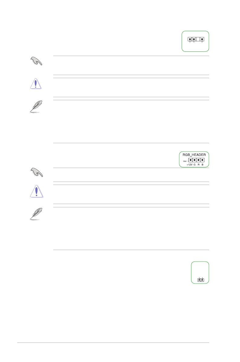
11. Aura RGB headers
The Aura RGB headers allow you to connect RGB LED strips.
The Aura RGB headers support 5050 RGB multi-color LED strips (12V/G/R/B), with a
maximum power rating of 3A (12V).
Before you install or remove any component, ensure that the ATX power supply is switched
off or the power cord is detached from the power supply. Failure to do so may cause severe
damage to the motherboard, peripherals, or components.
Actual lighting and color will vary with LED strip.
If your LED strip does not light up, check if the RGB LED extension cable and the
RGB LED strip are connected in the correct orientation, and the 12V connector is
aligned with the 12V header on the motherboard.
The LED strip will only light up when the system is powered on.
The LED strip is purchased separately.
12. Clear CMOS header
The Clear CMOS header allows you to clear the Real Time Clock (RTC) RAM in
the CMOS, which contains the date, time, system passwords, and system setup
parameters.
To erase the RTC RAM:
1. Turn OFF the computer and unplug the power cord.
2. Short-circuit pin 1-2 with a metal object or jumper cap for about 5-10 seconds.
3. Plug the power cord and turn ON the computer.
4. Hold down the <Del> key during the boot process and enter BIOS setup to
re-enter data.
ADD_GEN 2
+5V
Data
Ground
PIN 1
CLRTC
+3V_BAT
GND
PIN 1
Chapter 1: Product Introduction
1-5
DO NOT short-circuit the pins except when clearing the RTC RAM. Short-circuiting or
placing a jumper cap will cause system boot failure!
If the steps above do not help, remove the onboard button cell battery and short the two
pins again to clear the CMOS RTC RAM data. After clearing the CMOS, reinstall the button
cell battery.
13. COM Port header
The COM (Serial) Port header allows you to connect a COM port module.
Connect the COM port module cable to this header, then install the module to a
slot opening on the system chassis.
The COM port module is purchased separately.
14. Front Panel Audio header
The Front Panel Audio header is for a chassis-mounted front panel audio
I/O module that supports HD Audio. Connect one end of the front panel
audio I/O module cable to this header.
We recommend that you connect a high-denition front panel audio
module to this header to avail of the motherboard’s high-denition
audio capability.
15. S/PDIF Out header
The S/PDIF Out header allows you to connect the Sony/Philips Digital
Interface (S/PDIF) Out module.
The S/PDIF module is purchased separately.
16. Speaker header
The 4-pin header is for the chassis-mounted system warning speaker. The
speaker allows you to hear system beeps and warnings.
17. SPI TPM header
This header supports a Trusted Platform Module (TPM)
system with a Serial Peripheral Interface (SPI), allowing you
to securely store keys, digital certicates, passwords, and
data. A TPM system also helps enhance network security,
protects digital identities, and ensures platform integrity.
The TPM module is purchased separately.
PIN 1
COM
DCD
TXD
GND
RTS
RI
RXD
DTR
DSR
CTS
PORT1L
PORT1R
PORT2R
SENSE_SEND
PORT2L
AGND
NC
SENSE1_RETUR
SENSE2_RETUR
AAFP
PIN 1
HD-audio-compliant
pin definition
SPDIF_OUT
+5V
SPDIFOUT
GND
+5V
GND
GND
Speaker Out
SPEAKER
PIN 1
TPM
PIN 1
VCCSPI
S_PLTRST#
NC
F_SPI_PWR
F_SPI_CZS0#_R
T_SPI_MISO
F_SPI_HOLD#_R
S_SPI_TPM_IRQ#
S_SPI_TPM_CS2#
TPM_DETECT_L
GND
T_SPI_CLK
T_SPI_MOSI
PRIME H510M-A R2.0
1-6
18. 10-1 pin System Panel header
This header supports several chassis-mounted functions.
System Power LED header (+PWR_LED-)
The 2-pin header allows you to connect the System Power LED.
The System Power LED lights up when the system is connected
to a power source, or when you turn on the system power, and
blinks when the system is in sleep mode.
Storage Device Activity LED header (+HDD_LED-)
The 2-pin header allows you to connect the Storage Device Activity LED. The Storage
Device Activity LED lights up or blinks when data is read from or written to the storage
device or storage device add-on card.
Power Button/Soft-off Button header (PWR_BTN)
The 2-pin header allows you to connect the system power button. Press the power
button to power up the system, or put the system into sleep or soft-off mode
(depending on the operating system settings).
Reset button header (RESET)
The 2-pin header allows you to connect the chassis-mounted reset button. Press the
reset button to reboot the system.
PIN 1
PWR_BTN
PWR_LED+
PWR_LED-
PWR
GND
HDD_LED+
HDD_LED-
Ground
HWRST#
(NC)
F_PANEL
+PWR_LED-
+HDD_LED-RESET
Chapter 1: Product Introduction
1-7
1.2.2 Rear panel connectors
11
321 4 5
76 8 109
1. PS/2 Mouse (green) port. This port connects to a PS/2 mouse.
2. Video Graphics Adapter (VGA) port. This 15-pin port is for a VGA monitor or other
VGA-compatible devices.
3. Realtek 1Gb Ethernet port. This port allows 1Gbps Ethernet connection to a Local
Area Network (LAN) through a network hub. Refer to the table below for the Ethernet
port LED indications.
Speed LED
Status Description
OFF 10 Mbps connection
ORANGE 100 Mbps connection
GREEN 1 Gbps connection
Activity Link LED
Status Description
OFF No link
ORANGE Linked
BLINKING Data activity
ACT/LINK
LED
SPEED
LED
LAN port
Realtek 1Gb Ethernet port LED indications
4. Line In port (light blue). This port connects the tape, CD, DVD player, or other audio
sources.
5. Line Out port (lime). This port connects a headphone or a speaker. In 4-channel,
5.1-channel, and 7.1-channel congurations, the function of this port becomes Front
Speaker Out.
6. PS/2 Keyboard (purple) port. This port connects to a PS/2 keyboard.
7. HDMI™ port. This port is for a High-Denition Multimedia Interface (HDMI™)
connector, and is HDCP compliant allowing playback of HD DVD, Blu-ray, and other
protected content.
8. DisplayPort. This port is for a DisplayPort-compatible device.
9. USB 2.0 ports. These Universal Serial Bus (USB) ports are for USB 2.0 devices.
10. USB 3.2 Gen 1 (up to 5Gbps) ports. These Universal Serial Bus (USB) ports connect
to USB 3.2 Gen 1 devices.
PRIME H510M-A R2.0
1-8
11. Microphone port (pink). This port connects a microphone.
Refer to the audio conguration table for the function of the audio ports in 2, 4, 5.1, or
7.1-channel conguration.
Audio 2, 4, 5.1 or 7.1-channel conguration
Port 2-channel 4-channel 5.1-channel 7.1-channel
Light Blue
(Rear panel) -Rear Speaker
Out
Rear Speaker
Out
Rear Speaker
Out
Lime
(Rear panel)
Front Speaker
Out
Front Speaker
Out
Front Speaker
Out
Front Speaker
Out
Pink
(Rear panel) - - Center/Subwoofer Center/Subwoofer
Lime
(Front panel) - - - Side Speaker Out
Pink
(Front panel) ----
To configure a 7.1-channel audio output:
Use a chassis with HD audio module in the front panel to support a 7.1-channel audio
output.
Chapter 1: Product Introduction
1-9
1.3 Central Processing Unit (CPU)
This motherboard comes with a surface mount Intel® Socket LGA1200
designed for 11th Gen Intel® Core™ Processors & 10th Gen Intel®
Core™, Pentium® Gold and Celeron® Processors.
Unplug all power cables before installing the CPU.
Ensure that you install the correct CPU designed for the LGA1200 socket only. DO
NOT install a CPU designed for LGA1150, LGA1151, LGA1155 and LGA1156 sockets
on the LGA1200 socket.
Upon purchase of the motherboard, ensure that the PnP cap is on the socket and
the socket contacts are not bent. Contact your retailer immediately if the PnP cap
is missing, or if you see any damage to the PnP cap/socket contacts/motherboard
components.
Keep the cap after installing the motherboard. ASUS will process Return Merchandise
Authorization (RMA) requests only if the motherboard comes with the cap on the
LGA1200 socket.
The product warranty does not cover damage to the socket contacts resulting from
incorrect CPU installation/removal, or misplacement/loss/incorrect removal of the PnP
cap.
Installing the CPU
1
4
Apply the Thermal Interface Material to the CPU heatsink and CPU before you install the
heatsink and fan if necessary.
2
3
A
B
A
B
C
D
5
4
4
5
PRIME H510M-A R2.0
1-10
1.4 System memory
This motherboard comes with two Double Data Rate 4 (DDR4) Dual Inline Memory Module
(DIMM) sockets. The figure illustrates the location of the DDR4 DIMM sockets:
DIMM_A
DIMM_B
Channel Sockets
Channel A DIMM_A
Channel B DIMM_B
A DDR4 memory module is notched differently from a DDR, DDR2, or DDR3 module. DO
NOT install a DDR, DDR2, or DDR3 memory module to the DDR4 slot.
You may install varying memory sizes in Channel A and Channel B. The system maps the
total size of the lower-sized channel for the dual-channel conguration. Any excess memory
from the higher-sized channel is then mapped for single-channel operation.
The default memory operation frequency is dependent on its Serial Presence Detect
(SPD), which is the standard way of accessing information from a memory module.
Under the default state, some memory modules for overclocking may operate at a
lower frequency than the vendor-marked value.
For system stability, use a more efcient memory cooling system to support a full
memory load.
Always install DIMMs with the same CAS latency. For optimal compatibility, we
recommend that you install memory modules of the same version or date code (D/C)
from the same vendor. Check with the retailer to get the correct memory modules.
Supported memory types, data rate (speed), and number of DRAM modules vary
depending on the CPU and memory conguration, for more information please refer
to CPU/Memory Support list under the Support tab of product information site or visit
https://www.asus.com/support/.
Recommended memory congurations
DIMM_B
DIMM_ADIMM_A
DIMM_B
Chapter 1: Product Introduction
  • Page 1 1
  • Page 2 2
  • Page 3 3
  • Page 4 4
  • Page 5 5
  • Page 6 6
  • Page 7 7
  • Page 8 8
  • Page 9 9
  • Page 10 10
  • Page 11 11
  • Page 12 12
  • Page 13 13
  • Page 14 14
  • Page 15 15
  • Page 16 16
  • Page 17 17
  • Page 18 18
  • Page 19 19
  • Page 20 20
  • Page 21 21
  • Page 22 22
  • Page 23 23
  • Page 24 24
  • Page 25 25
  • Page 26 26
  • Page 27 27
  • Page 28 28
  • Page 29 29
  • Page 30 30
  • Page 31 31
  • Page 32 32
  • Page 33 33
  • Page 34 34

Asus PRIME H510M-A R2.0 Manual de utilizare

Categorie
Plăci de bază
Tip
Manual de utilizare
Acest manual este potrivit și pentru