
Compound Miter Saw
Kapp-und Gehrungssäge
º·ÏÙÛÔÎfiÙ˘ Ì ۷ÛÙ‹ ÎÂÊ·Ï‹
Pilarka
Gérvágó
Kombinovaná pila
Gönye kesme
Fierăstrău pentru tăieri înclinate
Stabilna krožna žaga
TopáoÇoäÌaÓ ÔËÎa
Read through carefully and understand these instructions before use.
Diese Anleitung vor Benutzung des Werkzeugs sorgfältig durchlesen und verstehen.
¢È·‚¿ÛÙ ÚÔÛÂÎÙÈο Î·È Î·Ù·ÓÔ‹ÛÂÙ ·˘Ù¤˜ ÙȘ Ô‰ËÁ›Â˜ ÚÈÓ ÙË ¯Ú‹ÛË.
Przed użytkowaniem należy dokładnie przeczytać niniejszą instrukcję i zrozumieć jej treść.
Használat előtt olvassa el figyelmesen a használati utasítást.
Před použitím si pečlivě přečtěte tento návod a ujistěte se, že mu dobře rozumíte.
Aleti kullanmadan önce bu kılavuzu iyice okuyun ve talimatları anlayın.
Înainte de utilizare, citiţi cu atenţie și înţelegeţi prezentele instrucţiuni.
Pred uporabo natančno preberite in razumite ta navodila.
BÌËÏaÚeÎëÌo ÔpoäÚËÚe ÀaÌÌyï ËÌcÚpyÍáËï Ôo íÍcÔÎyaÚaáËË ÔpeÊÀe äeÏ ÔoÎëÁoÇaÚëcÓ ËÌcÚpyÏeÌÚoÏ.
Handling instructions
Bedienungsanleitung
√‰ËÁ›Â˜ ¯ÂÈÚÈÛÌÔ‡
Instrukcja obsługi
Kezelési utasítás
Návod k obsluze
Kullanım talimatları
Instrucţiuni de utilizare
Navodila za rokovanje
àÌcÚpyÍáËÓ Ôo íÍcÔÎyaÚaáËË
C 10FCH2
•
C 10FCE2
001Cover_C10FCH2_EE 3/11/09, 20:071

1
1
2
34
5
8
9
67
8
7
8
7
3
B
C
D
E
F
G
H
I
J
K
1
2
4
0
8
7
6
5
9
A
M
L
R
Q
PO
N
1
5
S
T O
2
I
U U
VV
Q
X
P
W
R
00Table_C10FCH2_EE 3/11/09, 20:071

2
10 11
12
13
16 17
1514
Z
Y
a
^
]\
[
A
0
c
d
A
b
e
f
h
g
f
i
N
f
00Table_C10FCH2_EE 3/11/09, 20:072

3
18
21
22
23
24
j
C
D
E
B
20
ii
19
t
u
v
w
s
25
v
y
?
\ {
wx
z
b
H
Q
p
k
l
m
n o
[ q
k
m
nr
0
x
00Table_C10FCH2_EE 3/11/09, 20:073

4
26 27
28 29
30
31
32
ß
65
6 mm
17 mm
33
J
?
¶
D
•
ç
£
†
¢
J
§
|
}
~
†
ç
å
©
®
00Table_C10FCH2_EE 3/11/09, 20:074

5
English Deutsch Ελληνικά Polski
1 Handle Griff
2 Lock lever (C) Sperrhebel (C)
3 Motor Head Motorkopf
4 Gear Case Getriebegehäuse
5 Dust Bag Staubbeutel
6
Laser Marker Lasermarkierer
(Only C10FCH2) (Nur C10FCH2)
7 Turn Plate Drehplatte
8 6 mm Wing Bolt 6 mm-Flügelschraub
9 Vise Assembly Schraubstocksatz
: Sub Fence (B) Hilfsführung (B)
A Fence (B) Gitter (B)
B Turntable Drehbühne
C Side Handle Seitengriff
D Lever Hebel
E
Indicator (A) Zeiger (A)
(For miter scale) (Für Gehrungsskala)
F Table Insert Tischeinsatz
G Fence (A) Gitter (A)
H
Indicator (B) Anzeiger (B)
(For bevel scale) (Für Schrägschnittsskala)
I Lower Guard Unterer Schutz
J Saw Blade Sägeblatt
K Motor Motor
L Nameplate Typenschild
M Trigger Switch Auslöserschalter
N
Switch (For laser marker)
Schalter (Für Lasermarkierer)
(Only C10FCH2)
(Nur C10FCH2)
O Base Grundplatte
P Holder (B) Halter (B)
Q Clamp Lever Klemmhebel
R Locking Pin Verriegelungsstift
S Duct Kanal
T Right Angle Rechter Winkel
U Line Linie
V Warning Sign Warnsymbol
W 6 mm Bolt 6 mm-Schraube
X M6 × 20 Screw M6 × 20 Schraube
Y Screw Holder Schraubenhalter
Z 6 mm Wing Bolt (B) 6 mm-Flügelschraub (B)
[ Vise Shaft Schraubstockachse
\ 6 mm Wing Bolt (A) 6 mm-Flügelschraub (A)
] Workpiece Werkstück
` Vise Plate Schraubstockbacke
a Knob Knopf
b M6 Flat screw M6 Flache Schraube
c Plate (A) Platte (A)
d M6 Nylon nut M6 Nylon-Mutter
e M10 Bolt M10 Schraube
ερύλι
Μλς ασάλισης (C)
Κεαλή Μτέρ
Θήκη Ταυτήτων
Σακύλα Σκνης
∆είκτης λέιερ
(Μν για τ C10FCH2)
Περιστρική πλάκα
6 mm Φτερωτ Μπυλνι
Συγκρτηµα Μέγγενης
∆ευτερεύν %δηγς (B)
%δηγς (Β)
Περιστρική Πλάκα
Πλευρικ ερύλι
Μλς
∆είκτης (A)
(Για την κλίµακα λ+τµής)
Τεµάι τρδσίας
%δηγς (Α)
∆είκτης (B)
(Για επίπεδη κλίµακα)
Κάτω πρυλακτήρας
Πρινωτή Λάµα
Μτέρ
Πινακίδα
Σκανδάλη ∆ιακπτης
∆ιακπτης (Για τ δείκτη λέιερ)
(Μν για τ C10FCH2)
Βάση
Στήριγµα (B)
Μλς Σύσι+ης
Περνη Ασαλείας
Αγωγς
%ρθή γωνία
Γραµµή
Πρειδπιητικ σήµα
6 mm Μπυλνι
Βίδα M6 × 20
Στήριγµα Βίδας
6 mm Φτερωτ Μπυλνι (B)
Ά+νας µέγγενης
6 mm Φτερωτ Μπυλνι (A)
Αντικείµεν εργασίας
Πλάκα Μέγγενης
Κυµπί
Βίδα επίπεδης κεαλής M6
Πλάκα (A)
Πλαστικ περικλι M6
Μπυλνι M10
Rączka
Dźwignia blokady (C)
Głowica silnika
Obudowa przekładni
Worek pyłowy
Znacznik laserowy
(Tylko C10FCH2)
Tarcza obrotowa
Śruba skrzydełkowa 6 mm
Imadło
Podogranicznik (B)
Ogranicznik (B)
Podstawa obrotowa
Rączka boczna
Dźwignia
Wskaźnik (A)
(Dla skali uciosu)
Wkładka stołowa
Ogranicznik (A)
Wskaźnik (B)
(Dla skali cięcia ukośnego)
Osłona dolna
Ostrze piły
Silnik
Tabliczka znamionowa
Wyłącznik spustowy
Przełącznik (Dla znacznika
laserowego) (Tylko C10FCH2)
Podstawa
Uchwyt (B)
Dźwignia zaciskowa
Kołek blokujący
Osłona pierścieniowa
Kąt prawy
Linia
Znak ostrzegawczy
Śruba 6 mm
Śruba M6 × 20
Uchwyt śruby
Śruba skrzydełkowa 6 mm (B)
Wał imadła
Śruba skrzydełkowa 6 mm (A)
Przedmiot obrabiany
Tabliczka imadła
Gałka
Śruba płaska M6
Płytka (A)
Śruba nylonowa M6
Śruba M10
00Table_C10FCH2_EE 3/11/09, 20:075

6
English Deutsch Ελληνικά Polski
f Laser line Laserlinie
g Groove Nut
h 4 mm Hex. Bar Wrench
4 mm-Sechskantschlüssel
i Marking (pre-marked)
Markierung (vor-gekennzeichnet)
j Miter Scale Gehrungsskala
k
Holder (Optional accessory)
Halter (Sonderzubehör)
l Steel Square Stahlwinkel
m
6 mm Wing Nut
Flügelschraube, 6 mm
(Optional accessory)
(Sonderzubehör)
n
Height Adjustment Bolt 6 mm Höheneinstellschraube, 6 mm
(Optional accessory) (Sonderzubehör)
o Base Surface Grundfläche
p
6 mm Wing Bolt 6 mm-Flügelschraube
(Optional accessory) (Sonderzubehör)
q
Stopper Anschlag
(Optional accessory) (Sonderzubehör)
r
6 mm Wing Bolt 6 mm-Flügelschraube
(Optional accessory) (Sonderzubehör)
s 6 mm Wing Bolt 6 mm-Flügelschraube
Crown Molding Schraubstocksatz für
t Vise Ass’y Kronenform
(Optional accessory) (Sonderzubehör)
u 6 mm Wing Bolt 6 mm-Flügelschraube
v 6 mm Wing Bolt 6 mm-Flügelschraube
Crown Molding
Kronenformanschlag (L)
w Stopper (L)
(Sonderzubehör)
(Optional accessory)
Crown Molding
Kronenformanschlag (R)
x Stopper (R)
(Sonderzubehör)
(Optional accessory)
y 6 mm Knob Bolt 6 mm-Knopfschraube
z Knob Knopf
{ Crown molding Kronenform
| 4 mm Machine Screw
4 mm-Maschinenschraube
} Spindle Cover Spindelabdeckung
~ Spindle Lock Spindelhebel
å 10 mm Box Wrench 10 mm Steckschüssel
ç Washer (B) Unterlegscheibe (B)
† Bolt Schraube
¢ Washer Unterlegscheibe
£ Washer (A) Unterlegscheibe (A)
§ Color (A) Farbe (A)
• Hex. Head Bolt Sechskantschraube
¶ Steel Square Stahlwinkel
ß Wear limit line Verschleißgrenze
® Groove for Driver
Aussparung für Schraubendreher
© Brush Cap Bürstenkappe
Γραµµή λέιερ
Αυλάκωση
4 mm ε+αγωνικ κλειδί
Σηµάδι (πρσηµειωµέν)
Κλίµακα Λ+τµής
Στήριγµα (Πραιρετικ ε+άρτηµα)
Ατσαλένις Γνώµνας
6 mm Φτερωτ Πα+ιµάδι
(Πραιρετικ ε+άρτηµα)
Μπυλνι Ρύθµισης Ύψυς
6 mm (Πραιρετικ ε+άρτηµα)
Επιάνεια Βάσης
6 mm Φτερωτ µπυλνι
(Πραιρετικ ε+άρτηµα)
Αναστλέας
(Πραιρετικ ε+άρτηµα)
6 mm Φτερωτ Μπυλνι
(Πραιρετικ ε+άρτηµα)
6 mm Φτερωτ Μπυλνι
Συγκρτηµα Μέγγενης για τη
∆ιαµρωση Κρνίας
(Πραιρετικ ε+άρτηµα)
6 mm Φτερωτ Μπυλνι
6 mm Φτερωτ Μπυλνι
Αναστλέας ∆ιαµρωσης
Κρνίας
(L) (Πραιρετικ ε+άρτηµα)
Αναστλέας ∆ιαµρωσης
Κρνίας
(R) (Πραιρετικ ε+άρτηµα)
6 mm Κυµπί-Μπυλνι
Κυµπί
∆ιαµρωση Κρνίας
4 mm Κλίας
Κάλυµµα Ά+να
Ασάλεια Ά+να
10 mm Κίλ Κλειδί
Ρδέλα (Β)
Μπυλνι
Ρδέλα
Ρδέλα (Α)
ρώµα (A)
Ε+αγωνική κεαλή µπυλνιύ
Ατσαλένις Γνώµνας
:ρι θράς
Αυλάκωση για τν δηγ
Καπάκι για καρ;υνάκι
Linia lasera
Rowek
Klucz sześciokątny 4 mm
Oznaczenie
Skala uciosu
Uchwyt (Akcesorium opcjonalne)
Kątownik stalowy
Nakrętka motylkowa 6 mm
(Akcesorium opcjonalne)
Śruba regulacji wysokości 6 mm
(Akcesorium opcjonalne)
Powierzchnia podstawy
Śruba skrzydełkowa 6 mm
(Akcesorium opcjonalne)
Ogranicznik
(Akcesorium opcjonalne)
Śruba skrzydełkowa 6 mm
(Akcesorium opcjonalne)
Śruba skrzydełkowa 6 mm
Imadło do form
wypukłych
(Akcesorium opcjonalne)
Śruba skrzydełkowa 6 mm
Śruba skrzydełkowa 6 mm
Ogranicznik do form
wypukłych (L)
(Akcesorium opcjonalne)
Ogranicznik do form
wypukłych (R)
(Akcesorium opcjonalne)
Śruba gałkowa 6 mm
Gałka
Forma wypukła
Wkręt z rowkiem 4 mm
Pokrywa wrzeciona
Blokada wrzeciona
Klucz nasadowy 10 mm
Podkładka (B)
Śruba
Podkładka
Podkładka (A)
Kolor (A)
Śruba z główką sześciokątną
Kątownik stalowy
Linia dopuszczalnego zużycia
Rowek do członu napędowego
Nasadka na szczotkę
00Table_C10FCH2_EE 3/11/09, 20:076

7
Magyar Čeština Türkçe Română
1 Markolat Rukoje Mâner
2 Rögzítőkar (C) Blokovací páka (C) Manetă de blocare (C)
3 Motorfej Hlava motoru Capul motorului
4 Hajtásház Převodová skříň Carcasa motorului
5 Porzsák Sáček na prach Sac pentru praf
6
Lézeres jelölő Laserový značkovač Marcator cu laser
(Csak C10FCH2) (Pouze C10FCH2) (Numai C10FCH2)
7 Forgatólemez Otočná deska Placă rotativă
8 6 mm-es szárnyascsavar 6 mm křídlový šroub
Șurub de 6 mm cu cap fluture
9 Satuszerelvény Sestava svěráku Ansamblu menghină
? Alsó vezetőléc (B) Menší stavítko (B)
Element de limitare inferior (B)
A Vezetőléc (B) Stavítko (B) Element de limitare (B)
B Forgatóasztal Otočný stůl
Suprafaţă de lucru pivotantă
C Oldalsó markolat Boční rukoje Mâner lateral
D Kar Páčka Manetă
E
Jelző (A) Indikátor (A)
Indicator (A) (Pentru scala
(Sarokillesztési skálához) (Pro stupnici pokosu)
pentru tăiere înclinată)
F Asztalbetét Vložka stolu
Inserţie pentru suprafaţa de lucru
G Vezetőléc (A) Stavítko (A) Element de protecţie (A)
Jelző (B) Indikátor (B)
Indicator (B)
H
(Ferde illesztési skálához) (Pro stupnici úkosu)
(Pentru scala pentru
teșire unghiulară)
I Alsó védőburkolat Spodní ochranný kryt Apărătoare inferioară
J Fűrészlap Pilový kotouč Lama fierăstrăului
K Motor Motor Motor
L Névtábla Typový štítek Plăcuţă indicatoare
M Indítókapcsoló Spouštěcí spínač Comutator pentru pornire
N
Kapcsoló (Lézeres jelölőhöz)
Vypínač (Pro laserový značkovač)
Comutator (Pentru marcatorul
(Csak C10FCH2) (Pouze C10FCH2)
cu laser) (Numai C10FCH2)
O Alap Základová deska Placă de așezare
P Tartó (B) Držák (B) Suport (B)
Q Leszorító kar Páčka svorky Manetă de prindere
R Rögzítőcsapszeg Blokovací kolík Știft de blocare
S Csővezeték Potrubí Furtun
T Egyenes szög Pravý úhel Echer
U Vonal Přímka Linie
V Figyelmeztető búgás Varovný znak Semn de avertizare
W 6 mm csavar 6 mm šroub Șurub de 6 mm
X M6 × 20 csavar Šroub M6 × 20 Șurub M6 × 20
Y Csavartartó Držák šroubu Suport pentru șuruburi
Z
6 mm-es szárnyascsavar (B)
6 mm křídlový šroub (B)
Șurub de 6 mm cu cap fluture (B)
[ Satutengely Hřídel svěráku Arborele menghinei
\
6 mm-es szárnyascsavar (A)
6 mm křídlový šroub (A)
Șurub de 6 mm cu cap fluture (A)
] Munkadarab Obrobek Piesă de prelucrat
` Satutábla Deska svěráku Placa menghinei
a Gomb Knoflík Buton
b
M6 süllyesztett fejű csavar
Plochý šroub M6 Șurub M6 cu cap înecat
c Lemez (A) Deska (A) Placă (A)
d M6 nylon anya Nylonová matice M6 Piuliţă M6 din nailon
Sap
Kilit kolu (C)
Motor Baßlıåı
Dißli kutusu
Toz Torbası
Lazer Óßaretleyici
(Sadece C10FCH2)
Döner Taban
6 mm Kelebek Cıvata
Mengene Takımı
Alt Siper (B)
Siper (B)
Döner Taban
Yan Sap
Kol
Gösterge (A)
(Íev ölçeåine göre)
Masa Eklemesi
Siper (A)
Gösterge (B)
(Eåimli açı ölçeåine göre)
Alt Koruyucu
Testere bıçaåı
Motor
Marka Tabelası
Açma/Kapama Anahtarı
Anahtar (Lazer ißaretleyici için)
(Sadece C10FCH2)
Taban/Alt kısım
Tutamaç (B)
Mengene Kolu
Kilit Óånesi
Kanal
Dik Açı
Çizgi
Uyarı Óßareti
6 mm Cıvata
M6 × 20 Vida
Vida Tutamacı
6 mm Kelebek Cıvata (B)
Mengene Mili
6 mm Kelebek Cıvata (A)
Óß parçası
Mengene Tabanı
Tokmak Düåmesi
M6 Düz Vida
Plaka (A)
M6 Naylon somun
00Table_C10FCH2_EE 3/11/09, 20:077

8
Magyar Čeština Türkçe Română
e M10 csavar Šroub M10 Șurub M10
f Lézervonal Linie laseru Linie laser
g Horony Drážka Canelură
h 4 mm-es imbusz kulcs 4 mm šestiúhelníkový klíč
Cheie hexagonală de
4 mm cu mâner
i Jelölés (előre megjelölt) Značka Marcaj (pre-marcat)
j
Sarokillesztési skála (előre jelölt)
Stupnice pokosu Scală înclinată
k
Tartó Držák Suport
(Opcionális tartozék) (Doplňkové příslušenství) (Accesoriu opţional)
l Acél négyzet Ocelový úhelník Echer din oţel
m
6 mm-es szárnyas anya 6 mm křídlový šroub Piuliţă fluture de 6 mm
(Opcionális tartozék) (Doplňkové příslušenství) (Accesoriu opţional)
n
Magasságállító csavar 6 mm
Šroub pro nastavení výšky 6 mm
Șurub de 6 mm pentru reglarea
(Opcionális tartozék) (Doplňkové příslušenství)
înălţimii (accesoriu opţional)
o Alapfelület Povrch základové desky
Suprafaţa plăcii de așezare
p
6 mm-es szárnyascsavar 6 mm křídlový šroub
Șurub de 6 mm cu cap fluture
(Opcionális tartozék) (Doplňkové příslušenství)
(Accesoriu opţional)
q
Megállító Zarážka Opritor
(Opcionális tartozék) (Doplňkové příslušenství) (Accesoriu opţional)
r
6 mm-es szárnyascsavar 6 mm křídlový šroub
Șurub de 6 mm cu cap fluture
(Opcionális tartozék) (Doplňkové příslušenství)
(Accesoriu opţional)
s 6 mm-es szárnyascsavar 6 mm křídlový šroub
Șurub de 6 mm cu cap fluture
Koronás öntvény Svěrák zvonovnicového
Ansamblul dispozitivului pivotant
t satuszerelvény článku
de deplasare al menghinei
(Opcionális tartozék) (Doplňkové příslušenství)
(Accesoriu opţional)
u 6 mm-es szárnyascsavar 6 mm křídlový šroub
Șurub de 6 mm cu cap fluture
v 6 mm-es szárnyascsavar 6 mm křídlový šroub
Șurub de 6 mm cu cap fluture
w
Koronás öntvény megállító (L)
Zarážka zvonovnicového článku (L) Opritorul dispozitivului pivotant de
(Opcionális tartozék) (Doplňkové příslušenství)
deplasare (L) (Accesoriu opţional)
x
Koronás öntvény megállító (R)
Zarážka zvonovnicového článku (R) Opritorul dispozitivului pivotant de
(Opcionális tartozék) (Doplňkové příslušenství)
deplasare (R) (Accesoriu opţional)
y 6 mm gombos csavar 6 mm knoflíkový šroub
Șurub de 6 mm cu cap conic
z Gomb Knoflík Buton
{ Koronás öntvény Zvonovnicový článek
Dispozitiv pivotant de deplasare
| 4 mm-es gépcsavar 4 mm šroub stroje
Șurub de 4 mm al mașinii
} Tengelyfedél Kryt vřetena Carcasa axului
~ Tengelyrögzítő Blokování vřetena
Dispozitiv de blocare a axului
å 10 mm-es dugókulcs 10 mm nástrčný klíč Cheie inelară de 10 mm
ç Alátét (B) Podložka (B) Șaibă (B)
† Csavar Šroub Șurub
¢ Alátét Podložka Șaibă
£ Alátét (A) Podložka (A) Șaibă (A)
§ Szín (A) Barva (A) Culoare (A)
• Hatlapfejű csavar Šestiúhelníkový šroub Șurub cu cap hexagonal
¶ Acél négyzet Ocelový úhelník Echer din oţel
ß Kopási határvonal Čára limitu opotřebení Linie limită pentru uzură
® Csavarhúzó hornya
Drážka pro hnací mechanizmus
Canelură pentru șurubelniţă
© Kefesapka Uzávěr kartáče Capac pentru perie
M10 Cıvata
Lazer çizgisi
Oluk
4 mm Altıgen Çubuk
Anahtarı
Óßaret
Íev Ölçeåi
Tutamaç
(Ósteåe baålı gelen aksesuar)
Çelik Kare
6 mm Kelebek Cıvata
(Ósteåe baålı gelen aksesuar)
Yükseklik Ayar Cıvatası 6 mm
(Ósteåe baålı gelen aksesuar)
Taban Yüzey
6 mm Kelebek Cıvata
(Ósteåe baålı gelen aksesuar)
Durdurucu
(Ósteåe baålı gelen aksesuar)
6 mm Kelebek Cıvata
(Ósteåe baålı gelen aksesuar)
6 mm Kelebek Cıvata
Taç Kalıp Mengene
Takımı
(Ósteåe baålı gelen aksesuar)
6 mm Kelebek Cıvata
6 mm Kelebek Cıvata
Taç Kalıp Durdurucu (L)
(Ósteåe baålı gelen aksesuar)
Taç Kalıp Durdurucu (R)
(Ósteåe baålı gelen aksesuar)
6 mm Tokmak Cıvata
Kontrol Düåmesi
Taç kalıp
4 mm Makine Vidası
Mil kapaåı
Kilit iånesi
10 mm Lokma Anahtarı
Rondela (B)
Cıvata
Rondela
Rondela (A)
Renk (A)
Altıgen Baß Cıvata
Çelik Kare
Yıpranma limiti çizgisi
Uça göre oluk
Kömür Kapaåı
00Table_C10FCH2_EE 3/11/09, 20:078

9
Slovenščina PyccÍËÈ
1 Ročica
2 Ročica za zaklep (C)
3 Glava motorja
4 Pogonsko ohišje
5 Vreča za prah
6
Laserski označevalec
(Samo C10FCH2)
7 Obračalna plošča
8 6 mm sornik s krilci
9 Sestav primeža
? Stranska ograja (B)
A Ograja (B)
B Obračalna miza
C Stranska ročica
D Ročica
Indikator (A)
E
(Za zajerno merilo)
F Ploščni vstavek
G Ograja (A)
Indikator (B)
H
(Za poševno merilo)
I Spodnje varovalo
J Rezilo žage
K Motor
L Plošča z imenom
M Sprožilno stikalo
Stikalo (Za laserski
N označevalec)
(Samo C10FCH2)
O Podlaga
P Nosilec (B)
Q Ročica objemke
R Zaklepni zatič
S Vod
T Desni kot
U Linija
V Opozorilni znak
W 6 mm sornik
X Vijak M6 × 20
Y Nosilec vijaka
Z 6 mm sornik s krilci (B)
[ Gred primeža
\ 6 mm sornik s krilci (A)
] Obdelovalni kos
` Plošča primeža
a Gumb
b Ploski vijak M6
PyÍoÓÚÍa
ÅÎoÍËpoÇoäÌêÈ pêäaÖ (C)
ÉoÎoÇÍa ÀÇËÖaÚeÎÓ
KopÔyc ÔpËÇoÀa
èêÎecÄopÌËÍ
ãaÁepÌêÈ yÍaÁaÚeÎë
(ToÎëÍo C10FCH2)
èoÇopoÚÌaÓ ÔÎacÚËÌa
6 ÏÏ ÄapaåÍoÇêÈ ÄoÎÚ
ìÁeÎ ÚËcÍoÇ
BcÔoÏoÖaÚeÎëÌoe oÖpaÊÀeÌËe (B)
OÖpaÊÀeÌËe (B)
èoÇopoÚÌêÈ cÚoÎ
ÅoÍoÇaÓ pyÍoÓÚÍa
PêäaÖ
àÌÀËÍaÚop (A)
(ÑÎÓ åÍaÎê peÁaÌËÓ
ÔpË ÔoÇopoÚe)
BcÚaÇÍa cÚoÎa
OÖpaÊÀeÌËe (A)
àÌÀËÍaÚop (B)
(ÑÎÓ åÍaÎê peÁaÌËÓ
ÔpË ÌaÍÎoÌe)
HËÊÌee ÔpeÀoxpaÌËÚeÎëÌoe
ÔpËcÔocoÄÎeÌËe
èoÎoÚÌo ÔËÎê
MoÚop
èacÔopÚÌaÓ ÚaÄÎËäÍa
èycÍoÇoÈ ÔepeÍÎïäaÚeÎë
èepeÍÎïäaÚeÎë (ÑÎÓ
ÎaÁepÌoÖo yÍaÁaÚeÎÓ)
(ToÎëÍo C10FCH2)
OcÌoÇaÌËe
îËÍcaÚop (B)
ÂaÊËÏÌoÈ pêäaÖ
CÚoÔopÌaÓ åÔËÎëÍa
KopoÄ
èpÓÏoÈ yÖoÎ
MeÚÍa
èpeÀyÔpeÊÀaïçËÈ ÁÌaÍ
6 ÏÏ ÄoÎÚ
òypyÔ M6 × 20
BËÌÚoÇoÈ ÙËÍcaÚop
6 ÏÏ ÄapaåÍoÇêÈ ÄoÎÚ (B)
BaÎ ÚËcÍoÇ
6 ÏÏ ÄapaåÍoÇêÈ ÄoÎÚ (A)
ÂaÖoÚoÇÍa
èÎacÚËÌa ÚËcÍoÇ
PyÍoÓÚÍa
òypyÔ c ÔÎocÍoÈ ÖoÎoÇÍoÈ M6
00Table_C10FCH2_EE 3/11/09, 20:079

10
Slovenščina PyccÍËÈ
c Plošča (A)
d M6 najlonska matica
e Sornik M10
f Laserska linija
g Utor
h 4 mm heks. ključ droga
i Označba (predoznačeno)
j Zajerno merilo
k Nosilec (Opcijski dodatek)
l Jeklen kvadrat
m
6 mm matica s krilci
(Opcijski dodatek)
n
6 mm sornik za nastavljanje višine
(Opcijski dodatek)
o Površina podlage
p
6 mm sornik s krilci
(Opcijski dodatek)
q
Zaustavljalo
(Opcijski dodatek)
r
6 mm sornik s krilci
(Opcijski dodatek)
s 6 mm sornik s krilci
t
Primež kronaste oblike
(Opcijski dodatek)
u 6 mm sornik s krilci
v 6 mm sornik s krilci
w
Omejevalnik kronaste oblike (L)
(Opcijski dodatek)
x
Omejevalnik kronaste oblike (R)
(Opcijski dodatek)
y 6 mm izbočen sornik
z Gumb
{ Kronasta oblika
| 4 mm strojni vijak
} Pokrov gredi
~ Zaklep gredi
å 10 mm ključ
ç Tesnilo (B)
† Sornik
¢ Tesnilo
£ Tesnilo (A)
§ Barva (A)
• Sornik s heks. glavo
¶ Jeklen kvadrat
ß Omejevalna linija obrabe
® Utor za pogon
© Pokrov ščetke
èÎacÚËÌa (A)
HeÈÎoÌoÇaÓ ÖaÈÍa M6
ÅoÎÚ M10
ãËÌËÓ ÎaÁepa
èaÁ
4 ÏÏ åecÚËÖpaÌÌêÈ
ÚopáeÇoÈ ÖaeäÌêÈ ÍÎïä
MapÍËpoÇÍa
òÍaÎa peÁaÌËÓ ÔpË ÔoÇopoÚe
îËÍcaÚop
(ÀoÔoÎÌËÚeÎëÌaÓ ÔpËÌaÀÎeÊÌocÚë)
CÚaÎëÌoÈ yÖoÎëÌËÍ
6 ÏÏ ÄapaåÍoÇaÓ ÖaÈÍa
(ÀoÔoÎÌËÚeÎëÌaÓ ÔpËÌaÀÎeÊÌocÚë)
6 ÏÏ ÄoÎÚ peÖyÎËpoÇÍË ÇêcoÚê
(ÀoÔoÎÌËÚeÎëÌaÓ ÔpËÌaÀÎeÊÌocÚë)
OÔopÌaÓ ÔoÇepxÌocÚë
6 ÏÏ ÄapaåÍoÇêÈ ÄoÎÚ
(ÀoÔoÎÌËÚeÎëÌaÓ ÔpËÌaÀÎeÊÌocÚë)
CÚoÔop (ÀoÔoÎÌËÚeÎëÌaÓ
ÔpËÌaÀÎeÊÌocÚë)
6 ÏÏ ÄapaåÍoÇêÈ ÄoÎÚ
(ÀoÔoÎÌËÚeÎëÌaÓ ÔpËÌaÀÎeÊÌocÚë)
6 ÏÏ ÄapaåÍoÇêÈ ÄoÎÚ
ìÁeÎ ÚËcÍoÇ oÔpeccoÇÍË ÇeÌáa
(ÀoÔoÎÌËÚeÎëÌaÓ ÔpËÌaÀÎeÊÌocÚë)
6 ÏÏ ÄapaåÍoÇêÈ ÄoÎÚ
6 ÏÏ ÄapaåÍoÇêÈ ÄoÎÚ
CÚoÔop oÔpeccoÇÍË ÇeÌáa (L)
(ÀoÔoÎÌËÚeÎëÌaÓ ÔpËÌaÀÎeÊÌocÚë)
CÚoÔop oÔpeccoÇÍË ÇeÌáa (R)
(ÀoÔoÎÌËÚeÎëÌaÓ ÔpËÌaÀÎeÊÌocÚë)
6 ÏÏ åapoÇoÈ ÄoÎÚ
PyÍoÓÚÍa
OÔpeccoÇÍa ÇeÌáa
4 ÏÏ ÇËÌÚ cÚaÌÍa
óexoÎ åÔËÌÀeÎÓ
ÂaçeÎÍa åÔËÌÀeÎÓ
10 ÏÏ ÌaÍËÀÌoÈ ÍÎïä
èpoÏêÇaÚeÎë (B)
ÅoÎÚ
èpoÏêÇaÚeÎë
èpoÏêÇaÚeÎë (A)
ñÇeÚ (A)
òecÚËÖpaÌÌêÈ ÔepeÀÌËÈ ÄoÎÚ
CÚaÎëÌoÈ yÖoÎëÌËÍ
ãËÌËÓ ÔpeÀeÎëÌoÖo ËÁÌoca
èaÁ ÀÎÓ ÔpËÇoÀa
KoÎÔaäoÍ çeÚÍË
00Table_C10FCH2_EE 3/11/09, 20:0710

11
Symbols
WARNING
The following show
symbols used for the
machine. Be sure that
you understand their
meaning before use.
Symbole
WARNUNG
Die folgenden Symbole
werden für diese Maschine
verwendet. Achten Sie
darauf, diese vor der
Verwendung zu verstehen.
™‡Ì‚ÔÏ·
¶ƒ√™√Ã∏
Τα παρακάτω δείνυν τα
σύµ;λα πυ ρησιµπιύνται
στ µηάνηµα. Βε;αιωθείτε τι
κατανείτε τη σηµασίας τυς
πριν τη ρήση.
Symbole
OSTRZEŻENIE
Następujące oznaczenia to
symbole używane w instrukcji
obsługi maszyny. Upewnij się,
że rozumiesz ich znaczenie
zanim użyjesz narzędzia.
Read all safety
warnings and all
instructions.
Failure to follow the
warnings and
instructions may result
in electric shock, fire
and/or serious injury.
Lesen Sie sämtliche
Sicherheitshinweise und
Anweisungen durch.
Wenn die Warnungen
und Anweisungen nicht
befolgt werden, kann es
zu Stromschlag, Brand
und/oder ernsthaften
Verletzungen kommen.
¢È·‚¿˙ÂÙ fiϘ ÙȘ
ÚÔÂȉÔÔÈ‹ÛÂȘ ·ÛÊ·Ï›·˜
Î·È fiϘ ÙȘ Ô‰ËÁ›Â˜.
Η µη τήρηση των
πρειδπιήσεων και
δηγιών µπρεί να
πρκαλέσει
ηλεκτρπλη+ία, πυρκαγιά
και/ή σ;αρ τραυµατισµ.
Należy dokładnie zapoznać się
ze wszystkimi ostrzeżeniami i
wskazówkami
bezpieczeństwa.
Nieprzestrzeganie ostrzeżeń oraz
wskazówek bezpieczeństwa
może spowodować porażenie
prądem elektrycznym, pożar i/lub
odniesienie poważnych obrażeń.
Always wear eye
protection.
Tragen Sie immer
einen Augenschutz.
Φράτε πάντα τν
κατάλληλ ε+πλισµ
για την πρστασία
των µατιών.
Zawsze nosić okulary
ochronne.
Přečtěte si všechna varování
týkající se bezpečnosti a
všechny pokyny.
Nedodržení těchto varování a
pokynů může mít za následek
elektrický šok, požár a/nebo
vážné zranění.
Vždy noste ochranu
očí.
Tüm güvenlik uyarılarını
ve tüm talimatları okuyun.
Uyarılara ve talimatlara
uyulmaması elektrik
çarpmasına, yangına ve/
veya ciddi yaralanmaya
neden olabilir.
Daima koruyucu
gözlük takın.
èpoäÚËÚe Çce ÔpaÇËÎa
ÄeÁoÔacÌocÚË Ë ËÌcÚpyÍáËË.
He ÇêÔoÎÌeÌËe ÔpaÇËÎ Ë
ËÌcÚpyÍáËÈ ÏoÊeÚ ÔpËÇecÚË Í
ÔopaÊeÌËï íÎeÍÚpËäecÍËÏ
ÚoÍoÏ, ÔoÊapy Ë/ËÎË
cepëeÁÌoÈ ÚpaÇÏe.
BceÖÀa ÌaÀeÇaÈÚe
cpeÀcÚÇa ÁaçËÚê
ÖÎaÁ.
Symboly
UPOZORNĚNÍ
Následující text obsahuje
symboly, které jsou použity
na zařízení. Ujistěte se, že
rozumíte jejich obsahu
před tím, než začnete
zařízení používat.
Simgeler
DÓKKAT
Aßaåıda, bu alet için kullanılan
simgeler gösterilmißtir. Aleti
kullanmadan önce bu
simgelerin ne anlama geldiåini
anladıåınızdan emin olun.
CËÏÇoÎê
èPEÑìèPEÜÑEHàE
HËÊe ÔpËÇeÀeÌê cËÏÇoÎê,
ËcÔoÎëÁyeÏêe ÀÎÓ
ÏaåËÌê. èepeÀ ÌaäaÎoÏ
paÄoÚê oÄÓÁaÚeÎëÌo
yÄeÀËÚecë Ç ÚoÏ, äÚo Bê
ÔoÌËÏaeÚe Ëx ÁÌaäeÌËe.
Only for EU countries
Do not dispose of electric tools
together with household waste
material!
In observance of European
Directive 2002/96/EC on waste
electrical and electronic
equipment and its
implementation in accordance
with national law, electric tools
that have reached the end of
their life must be collected
separately and returned to an
environmentally compatible
recycling facility.
Nur für EU-Länder
Werfen Sie
Elektrowerkzeuge nicht in
den Hausmüll!
Gemäss Europäischer
Richtlinie 2002/96/EG über
Elektro- und Elektronik-
Altgeräte und Umsetzung
in nationales Recht
müssen verbrauchte
Elektrowerkzeuge
getrennt gesammelt und
einer umweltgerechten
Wiederververtung
zugeführt werden.
Mvo για τις ώρες της EE
Mηv πετάτε τα ηλεκτρικά
εργαλεία στov κάδo
oικιακώv απoρριµµάτωv!
Σύµωvα µε τηv εuρωπαϊκή
oδηγία 2002/96/EK περί
ηλεκτρικώv και
ηλεκτρovικώv σuσκεuώv και
τηv εvσωµάτωσή της στo
εθvικ δίκαιo, τα ηλεκτρικά
εργαλεία πρέπει vα
σuλλέγovται +εωριστά και
vα επιστρέovται για
αvακύκλωση µε τρπo
ιλικ πρoς τo περι;άλλov.
Dotyczy tylko państw UE
Nie wyrzucaj elektronarzędzi
wraz z odpadami z
gospodarstwa domowego!
Zgodnie z Europejską
Dyrektywą 2002/96/WE w
sprawie zużytego sprzętu
elektrotechnicznego i
elektronicznego oraz
dostosowaniem jej do
prawa krajowego, zużyte
elektronarzędzia należy
posegregować i zutylizować
w sposób przyjazny dla
środowiska.
Jen pro státy EU
Elektrické nářadí
nevyhazujte do
komunálního odpadu!
Podle evropské směrnice
2002/96/EG o nakládání s
použitými elektrickými a
elektronickými zařízeními a
odpovídajících ustanovení
právních předpisů
jednotlivých zemí se
použitá elektrická nářadí
musí sbírat odděleně od
ostatního odpadu a
podrobit ekologicky
šetrnému recyklování.
Sadece AB ülkeleri için
Elektrikli el aletlerini evdeki
çöp kutusuna atmayınız!
Kullanılmıß elektrikli
aletleri, elektrik ve
elektronikli eski cihazlar
hakkındaki 2002/96/EC
Avrupa yönergelerine göre
ve bu yönergeler ulusal
hukuk kurallarına göre
uyarlanarak, ayrı olarak
toplanmalı ve çevre
ßartlarına uygun bir ßekilde
tekrar deåerlendirmeye
gönderilmelidir.
ToÎëÍo ÀÎÓ cÚpaÌ EC
He ÇêÍËÀêÇaÈÚe
íÎeÍÚpoÔpËÄopê ÇÏecÚe c
oÄoêäÌêÏ ÏycopoÏ!
B cooÚÇeÚcÚÇËË c
eÇpoÔeÈcÍoÈ ÀËpeÍÚËÇoÈ
2002/96/EG oÄ yÚËÎËÁaáËË
cÚapêx íÎeÍÚpËäecÍËx Ë
íÎeÍÚpoÌÌêx ÔpËÄopoÇ Ë Ç
cooÚÇeÚcÚÇËË c ÏecÚÌêÏË
ÁaÍoÌaÏË íÎeÍÚpoÔpËÄopê,
ÄêÇçËe Ç íÍcÔÎyaÚaáËË,
ÀoÎÊÌê yÚËÎËÁoÇêÇaÚëcÓ
oÚÀeÎëÌo ÄeÁoÔacÌêÏ ÀÎÓ
oÍpyÊaïçeÈ cpeÀê
cÔocoÄoÏ.
Jelölések
FIGYELEM
Az alábbiakban a géphez
alkalmazott jelölések vannak
felsorolva. A gép használata
előtt feltétlenül ismerje meg
ezeket a jelöléseket.
Mindig viseljen
védőszemüveget.
Csak EU-országok
számára
Az elektromos
kéziszerszámokat ne dobja
a háztartási szemétbe!
A használt villamos és
elektronikai készülékekről
szóló 2002/96/EK irányelv
és annak a nemzeti jogba
való átültetése szerint az
elhasznált elektromos
kéziszerszámokat külön
kell gyűjteni, és
környezetbarát módon újra
kell hasznosítani.
Olvasson el minden
biztonsági
figyelmeztetést és
minden utasítást.
A figyelmeztetések és
utasítások be nem
tartása áramütést, tüzet
és/vagy súlyos sérülést
eredményezhet.
Preberite vas varnostna
opozorila in navodila.
Z neupoštevanjem opozoril
in navodil tvegate električni
udar, požar in/ali resne
telesne poškodbe.
Uporaba zaščite za
oči je obvezna.
Simboli
OPOZORILO
V nadaljevanju so
prikazani simboli,
uporabljeni pri stroju.
Pred uporabo se
prepričajte, da jih
razumete.
Samo za države EU
Električnih orodij ne
zavržite skupaj z
gospodinjskimi odpadki!
V skladu z evropsko
direktivo 2002/96/EC o
odpadni električni in
elektronski opremi in
izvedbi v skladu z
državnimi zakoni, je
treba električna orodja,
ki so dosegla življenjsko
dobo ločeno zbirati in
vrniti v z okoljem
združljivo ustanovo za
recikliranje.
Citiţi toate avertismentele
privind siguranţa și toate
instrucţiunile.
Nerespectarea avertismentelor și a
instrucţiunilor poate avea ca efect
producerea de șocuri electrice,
incendii și/sau vătămări grave.
Purtaţi întotdeauna
protecţie pentru ochi.
Simboluri
AVERTISMENT
În cele ce urmează sunt
prezentate simbolurile
folosite pentru mașină.
Înainte de utilizare,
asiguraţi-vă că înţelegeţi
semnificaţia acestora.
Numai pentru ţările membre UE
Nu aruncaţi această sculă
electrică împreună cu deșeurile
menajere!
În conformitate cu Directiva
Europeană 2002/96/CE referitoare
la deșeurile reprezentând
echipamente electrice și
electronice și la implementarea
acesteia în conformitate cu
legislaţiile naţionale, sculele
electrice care au ajuns la finalul
duratei de folosire trebuie
colectate separat și duse la o
unitate de reciclare compatibilă cu
mediul înconjurător.
Vždy používejte
chrániče sluchu.
Daima koruyucu
kulaklık takın.
BceÖÀa ÌaÀeÇaÈÚe
cpeÀcÚÇa ÁaçËÚê
opÖaÌoÇ cÎyxa.
Purtaţi întotdeauna
protecţie auditivă.
Obvezna je uporaba
zaščite za ušesa.
Always wear
hearing protection.
Stets Gehörschutz
tragen.
Φράτε πάντα
πρστατευτικά ακής.
Zawsze nosić
słuchawki ochronne.
Mindig viseljen a hallást
védő védőfelszerelést.
00Table_C10FCH2_EE 3/11/09, 20:0711

12
English
GENERAL OPERATIONAL PRECAUTIONS
WARNING! When using electric tools, basic safety
precautions should always be followed to reduce the risk
of fire, electric shock and personal injury, including the
following.
Read all these instructions before operating this product
and save these instructions.
For safe operations:
1. Keep work area clean. Cluttered areas and benches
invite injuries.
2. Consider work area environment. Do not expose
power tools to rain. Do not use power tools in damp
or wet locations. Keep work area well lit.
Do not use power tools where there is risk to cause
fire or explosion.
3. Guard against electric shock. Avoid body contact
with earthed or grounded surfaces (e.g. pipes,
radiators, ranges, refrigerators).
4. Keep children and infirm persons away. Do not let
visitors touch the tool or extension cord. All visitors
should be kept away from work area.
5. Store idle tools. When not in use, tools should be
stored in a dry, high or locked up place, out of reach
of children and infirm persons.
6. Do not force the tool. It will do the job better and
safer at the rate for which it was intended.
7. Use the right tool. Do not force small tools or
attachments to do the job of a heavy duty tool. Do
not use tools for purposes not intended; for example,
do not use circular saw to cut tree limbs or logs.
8. Dress properly. Do not wear loose clothing or
jewelry, they can be caught in moving parts. Rubber
gloves and non-skid footwear are recommended
when working outdoors. Wear protecting hair
covering to contain long hair.
9. Use eye protection. Also use face or dust mask if
the cutting operation is dusty.
10. Connect dust extraction equipment.
Cutting operation by this compound miter saw may
produce considerable amount of dust from
extraction duct on fixed guard.
(Dust material: Wood or Aluminium)
If devices are provided for the connection of dust
extraction and collection facilities ensure these are
connected and properly used.
11. Do not abuse the cord. Never carry the tool by the
cord or yank it to disconnect it from the receptacle.
Keep the cord away from heat, oil and sharp edges.
12. Secure work. Use clamps or a vise to hold the work.
It is safer than using your hand and it frees both
hands to operate tool.
13. Do not overreach. Keep proper footing and balance
at all times.
14. Maintain tools with care. Keep cutting tools sharp
and clean for better and safer performance. Follow
instructions for lubrication and changing
accessories. Inspect tool cords periodically and if
damaged, have it repaired by authorized service
center. Inspect extension cords periodically and
replace, if damaged. Keep handles dry, clean, and
free from oil and grease.
15. Disconnect tools. When not in use, before servicing,
and when changing accessories such as blades, bits
and cutters.
16. Remove adjusting keys and wrenches. Form the
habit of checking to see that keys and adjusting
wrenches are removed from the tool before turning
it on.
17. Avoid unintentional starting. Do not carry a plugged-
in tool with a finger on the switch. Ensure switch is
off when plugging in.
18. Use outdoor extension leads. When tool is used
outdoors, use only extension cords intended for
outdoor use.
19. Stay alert. Watch what you are doing. Use common
sense. Do not operate tool when you are tired.
20. Check damaged parts. Before further use of the tool,
a guard or other part that is damaged should be
carefully checked to determine that it will operate
properly and perform its intended function. Check
for alignment of moving parts, free running of
moving parts, breakage of parts, mounting and any
other conditions that may affect its operation. A
guard or other part that is damaged should be
properly repaired or replaced by an authorized
service center unless otherwise indicated in this
handling instructions. Have defective switches
replaced by an authorized service center. Do not use
the tool if the switch does not turn it on and off.
21. Warning
The use of any accessory or attachment, other than
those recommended in this handling instructions,
may present a risk of personal injury.
22. Have your tool repaired by a qualified person.
This electric tool is in accordance with the relevant
safety requirements. Repairs should only be carried
out by qualified persons using original spare parts.
Otherwise this may result in considerable danger
to the user.
PRECAUTIONS ON USING COMPOUND MITER SAW
1. Keep the floor area around the machine level. Well
maintained and free of loose materials e.g. chips
and cut-offs.
2. Provide adequate general or localized lighting.
3. Do not use power tools for applications other than
those specified in the handling instructions.
4. Repairing must be done only by authorized service
facility. Manufacturer is not responsible for any
damages and injuries due to the repair by the
unauthorized persons as well as the mishandling of
the tool.
5. To ensure the designed operational integrity of
power tools, do not remove installed covers or
screws.
6. Do not touch movable parts or accessories unless
the power source has been disconnected.
7. Use your tool at lower input than specified on the
nameplate; otherwise, the finish may be spoiled and
working efficiency reduced due to motor overload.
8. Do not wipe plastic parts with solvent. Solvents such
as gasoline, thinner, benzine, carbon tetrachloride,
alcohol, may damage and crack plastic parts. Do not
wipe them with such solvent. Clean plastic parts with
a soft cloth lightly dampened with soapy water.
9. Use only original HITACHI replacement parts.
10. This tool should only be disassembled for
replacement of carbon brushes.
11. The exploded assembly drawing on this handling
instructions should be used only for authorized
service facility.
12. Never cut ferrous metals or masonry.
13. Adequate general or localized lighting is provided.
Stock and finished workpieces are located close to
the operators normal working position.
14. Wear suitable personal protective equipment when
necessary, this could include:
Hearing protection to reduce the risk of induced
hearing loss.
Eye protection to reduce the risk of injuring an eye.
Respiratory protection to reduce the risk of
inhalation of harmful dust.
01Eng_C10FCH2_EE 3/11/09, 20:0712

13
English
Gloves for handling saw blades (saw blades shall
be carried in a holder wherever practicable) and
rough material.
15. The operator is adequately trained in the use,
adjustment and operation of the machine.
16. Refrain from removing any cut-offs or other parts
of the workpiece from the cutting area whilst the
machine is running and the saw head is not in the
rest position.
17. Never use the compound miter saw with its lower
guard locked in the open position.
18. Ensure that the lower guard moves smoothly.
19. Do not use the saw without guards in position, in
good working order and properly maintained.
20. Use correctly sharpened saw blades. Observe the
maximum speed marked on the saw blade.
21. Do not use saw blades which are damaged or
deformed.
22. Do not use saw blades manufactured from high
speed steel.
23. Use only saw blades recommended by HITACHI.
Use of saw blade comply with EN847-1.
24. The saw blades should be from 235 mm to 255 mm
external diameter ranges.
25. Select the correct saw blade for the material to be
cut.
26. Never operate the compound miter saw with the
saw blade turned upward or to the side.
27. Ensure that the workpiece is free of foreign matter
such as nails.
28. Replace the table insert when worn.
29. Do not use the saw to cut other than aluminium,
wood or similar materials.
30. Do not use the saw to cut other materials than those
recommended by the manufacturer.
31. Blade replacement procedure, including the method
for repositioning and a warning that this must be
carried out correctly.
32. Connect the compound miter saw to a dust
collecting device when sawing wood.
33. Take care when slotting.
34. When transporting or carrying the tool, do not grasp
the holder. Grasp the handle instead of the holder.
35. Start cutting only after motor revolution reaches
maximum speed.
36. Promptly cut OFF the switch when abnormality
observed.
37. Shut off power and wait for saw blade to stop before
servicing or adjusting tool.
38. During a miter or bevel cut the blade should not be
lifted until it has stopped rotation completely.
39. Take all the possibility of residual risks in cutting
operation into your consideration, such as the laser
radiation to your eyes, the inadvertent access to
moving parts on slide mechanical parts on machine
and so on.
SPECIFICATIONS
* Be sure to check the nameplate on product as it is subject to change by areas.
59 mm × 144 mm
0° or
89 mm × 101 mm
Miter 45° 59 mm × 102 mm
Bevel Left 45° 41 mm × 144 mm
Compound (Bevel Left 45°, Miter 45°)
41 mm × 102 mm
Saw Blade Dimensions (oD × iD × Thickness) 255 mm × 30 mm × 2.3 mm
Miter Cutting Angle Right and Left 0° – 52°
Bevel Cutting Angle Left 0° – 45°
Compound Cutting Angle Miter (Right and Left) 0° – 45°
Voltage (by areas)* (110 V, 230 V)
Power Input* 1520 W
No-Load Speed 5000 min
–1
Machine Dimensions (Width × Depth × Height) 460 mm × 628 mm × 561 mm
Weight (Net) 12 kg (C10FCH2) / 11.9 kg (C10FCE2)
Maximum output Po<3 mW Class Laser Product
(Iambda) 654 nm
Laser medium Laser Diode
Max. Cutting
Capacity
Height × Width
Laser Marker
(Only Model C10FCH2)
STANDARD ACCESSORIES
(1) 255 mm TCT Saw blade (mounted on tool) ............. 1
(2) Dust bag ...................................................................... 1
(3) 10 mm Box wrench .................................................... 1
(4) Vise Assembly ............................................................ 1
(5) 4 mm Hex. bar wrench (only C10FCH2) ................... 1
(6) Sub Fence (B) ............................................................. 1
(7) Flat screw .................................................................... 1
(8) M6 Nylon nut .............................................................. 1
(9) Plate (A) ....................................................................... 1
(10) Holder (B) .................................................................. 1
(11) Side handle ............................................................... 1
Standard accessories are subject to change without
notice.
01Eng_C10FCH2_EE 3/11/09, 20:0713

14
English
OPTIONAL ACCESSORIES (SOLD SEPARATELY)
(1) Extension Holder and Stopper
(2) Crown molding Vise Ass'y (Include Crown molding
Stopper (L))
(3) Crown molding Stopper (L)
(4) Crown molding Stopper (R)
Optional accessories are subject to change without notice.
APPLICATION
䡬 Cutting various types of aluminium sash and wood.
UNPACKING
䡬 Carefully unpack the power tool and all related items
(standard accessories).
䡬 Check carefully to make certain all related items
(standard accessories) are present.
PRIOR TO OPERATION
1. Power source
Ensure that the power source to be utilized conforms
to the power requirements specified on the product
nameplate.
2. Power switch
Ensure that the power switch is in the OFF position. If
the plug is connected to a receptacle while the trigger
switch is in the ON position, the power tool will start
operating immediately, inviting serious accident.
3. Extension cord
When the work area is removed from the power
source, use an extension cord of sufficient thickness
and rated capacity. The extension cord should be kept
as short as practicable.
4. When the power tool is prepared for shipping, its
main parts are secured by a locking pin
Move the handle slightly so that the locking pin can
be disengaged.
CAUTION
䡬 Set for transport
Lock the locking pin into the gear case (Fig. 3).
Remove a 6 mm wing bolt.Turn the turn plate as the
Fig. 5, and fix it again with the 6 mm wing bolt.
Lower guard cover the teeth of the blade to the front
of the machine.
䡬 Cutting work
Move the handle slightly so that the locking pin can
be disengaged.
Remove a 6 mm wing bolt.Turn the turn plate as Fig.
6, and fix it again with the 6 mm wing bolt.
5. Attach the dust bag to the main unit (Fig. 1)
(1) When the dust bag has become full of sawdust, dust
will be blown out of the dust bag when the saw blade
rotates.
Check the dust bag periodically and empty it before it
becomes full.
(2) During bevel and compound cutting, attach the dust
bag at a right angle to the base surface as shown in
Fig. 4.
CAUTION
䡬 Empty the dust bag frequently to prevent the duct and
the safety cover from becoming clogged.
Sawdust will accumulate more quickly than normal
during bevel cutting.
6. Installation
Ensure that the machine is always fixed to bench.
Attach the power tool to a level, horizontal work bench.
Select 8 mm diameter bolts suitable in length for the
thickness of the work bench.
Bolt length should be at least 35 mm plus the thickness
of the work bench.
For example, use 8 mm × 60 mm bolts for a 25 mm
thick work bench.
ADJUSTING THE POWER TOOL PRIOR TO USE
CAUTION
Make all necessary adjustments before inserting the
plug in the power source.
1. Check to see that the lower guard operates smoothly
CAUTION
䡬 This compound miter saw is equipped with a saw
head lock as safety device.
䡬 To lower the saw head to cut, the lock must be released
by pressing the lock lever (C) with your thumb.
(1) When you push down the handle while pushing the
lock lever (C), check that the lower guard revolves
smoothly (Fig. 7).
(2) Next, check that the lower guard returns to the original
position when the handle is raised.
PRACTICAL APPLICATIONS
WARNING
䡬 To avoid personal injury, never remove or place a
workpiece on the table while the tool is being
operated.
䡬 Never place your limbs inside of the line next to
warning sign while the tool is being operated. This
may cause hazardous conditions (see Fig. 8).
CAUTION
䡬 It is dangerous to remove or install the workpiece
while the saw blade is turning.
䡬 When sawing, clean off the shavings from the
turntable.
䡬 If the shavings accumulate too much, the saw blade
from the cutting material will be exposed. Never
subject your hand or anything else to go near the
exposed blade.
1. Tightly secure the material by vise assembly to be
cut so that it does not move during cutting
2. Switch operation
Pulling the trigger turns the switch on. Releasing the
trigger turns the switch off.
3. Holder (B), clamp lever adjustment (Fig. 9)
Attach the included holder (B) in the position as shown
in Fig. 9 and adjust the holder (B) until its bottom
surface contacts the work bench surface. After
adjustments, securely tighten the 6mm bolt with the
included 10mm box wrench. Loosen the M6 × 20 screw
on the clamp lever and attach to a position where the
clamp lever can be easily operated.
4. Using the Vise Assembly (Standard accessory) (Fig. 10)
(1) The vise assembly can be mounted on either the left
fence {Fence (B)} or the right fence {Fence (A)} by
loosening the 6 mm wing bolt (A).
(2) The screw holder can be raised or lowered according
to the height of the workpiece by loosening the 6 mm
wing bolt (B). After the adjustment, firmly tighten the
6 mm wing bolt (B) and fix the screw holder.
01Eng_C10FCH2_EE 3/11/09, 20:0714

15
English
(3) Turn the upper knob and securely fix the workpiece
in position.
WARNING
䡬 Always firmly clamp or vise to secure the workpiece
to the fence; otherwise the workpiece might be thrust
from the table and cause bodily harm.
CAUTION
䡬 Always confirm that the motor head does not contact
the vise assembly when it is lowered for cutting. If
there is any danger that it may do so, loosen the 6
mm wing bolt and move the vise assembly to a
position where it will not contact the saw blade.
5. Install the sub fence (B) (Fig. 11)
In the case of direct angle cutting and angle cutting,
use the sub fence. The sub fence (B) can be installed
on the right side of the guide fence (B). Place the
attached plate (A) in the position as shown in Fig. 11,
insert the tip in the groove of fence (B) and
simultaneously, insert flathead screw M6 into fence (B),
sub fence (B), and plate (A), then tighten nylon nut M6
with the included 10mm box wrench until the sub fence
(B) can smoothly rotate. Then, you can realize stable
cutting of the material with a wide back face.
WARNING
In the case of left bevel cutting, rotate the sub fence
(B). Supposing it is not able to rotate it, it will contact
the blade or some part of the tool, causing in serious
injury to operator.
6. Using an ink line
Upon lowering the motor section, the lower guard is
raised and the saw blade appears.
Align the ink line with the saw blade.
CAUTION
Never lift the lower guard while the saw blade is
rotating.
The sub fence will not only make contact and
adversely affect cutting accuracy, this could also result
in damage to the guard.
7. Install the side handle (Fig. 12)
Remove the M10 bolt and install the side handle that
came enclosed with this unit.
8. Position adjustment of laser line (Only Model
C10FCH2)
Ink lining can be easily made on this tool to the laser
marker. A switch lights up the laser marker (Fig. 13).
Depending upon your cutting choice, the laser line
can be aligned with the left side of the cutting width
(saw blade) or the ink line on the right side.
The laser line is adjusted to the width of the saw blade
at the time of factory shipment. Adjust the positions
of the saw blade and the laser line taking the following
steps to suit the use of your choice.
(1) Light up the laser marker and make a groove of about 5
mm deep on the workpiece that is about 38 mm in height
and 89 mm in width. Hold the grooved workpiece by vise
as it is and do not move it.
(2) Then insert a 4 mm hex. bar wrench in the 12 diameter
hole on the side of the gear case, turn the hex. socket
set screw to move the laser line. (If you turn the Hex.
socket screw clockwise, the laser line will shift to the
right and if you turn it counterclockwise, the laser line
will shift to the left.) When you work with the ink line
aligned with the left side of the saw blade, align the
laser line with the left end of the groove (Fig. 14). When
you align it with the right side of the saw blade, align
the laser line with the right side of the groove.
(3) After adjusting the position of the laser line, draw a
right-angle ink line on the workpiece and align the
ink line with the laser line. When aligning the ink line,
slide the workpiece little by little and secure it by vise
at a position where the laser line overlaps with the
ink line. Work on the grooving again and check the
position of the laser line. If you wish to change the
laser line’s position, make adjustments again
following the steps from (1) to (3).
WARNING (Fig. 16 and Fig. 17)
䡬 Make sure before plugging the power plug into the
receptacle that the main body and the laser marker
are turned off.
䡬 Exercise utmost caution in handling a switch trigger for
the position adjustment of the laser line, as the power
plug is plugged into the receptacle during operation.
If the switch trigger is pulled inadvertently, the saw
blade can rotate and result in unexpected accidents.
䡬 Do not remove the laser marker to be used for other
purposes.
CAUTION
䡬 Laser radiation - Do not stare into beam.
䡬 Laser radiation on work table. Do not stare into beam.
If your eye is exposed directly to the laser beam, it
can be hurt.
䡬 Do not dismantle it.
䡬 Do not give strong impact to the laser marker (main
body of tool); otherwise, the position of a laser line
can go out of order, resulting in the damage of the
laser marker as well as a shortened service life.
䡬 Keep the laser marker lit only during a cutting
operation. Prolonged lighting of the laser marker can
result in a shortened service life.
䡬 Use of controls or adjustments or performance of
procedures other than those specified herein may
result in hazardous radiation exposure.
NOTE
䡬 Perform cutting by overlapping the ink line with the
laser line.
䡬 When the ink line and the laser line are overlapped,
the strength and weakness of light will change,
resulting in a stable cutting operation because you
can easily discern the conformity of lines. This ensures
the minimum cutting errors.
䡬 In outdoor or near-the-window operations, it may
become difficult to observe the laser line due to the
sunlight. Under such circumstances, move to a place
that is not directly under the sunlight and engage in
the operation.
䡬 Do not tug on the cord behind the motor head or hook
your finger, wood and the like around it; otherwise,
the cord may come off and the laser marker may not
be lit up.
䡬 Check and make sure on a periodic basis if the position
of the laser line is in order. As regards the checking
method, draw a right-angle ink line on the workpiece
with the height of about 38 mm and the width of 89
mm, and check that the laser line is in line with the
ink line [The deviation between the ink line and the
laser line should be less than the ink line width (0.5
mm)] (Fig. 15).
9. Cutting operation
(1) As shown in Fig. 18 the width of the saw blade is the
width of the cut. Therefore, slide the workpiece to the
right (viewed from the operator’s position) when
length
is desired, or to the left when length is
desired.
01Eng_C10FCH2_EE 3/11/09, 20:0715

16
English
(Only Model C10FCH2)
If a laser marker is used, align the laser line with the
left side of the saw blade, and then align the ink line
with the laser line.
(2) Once the saw blade reaches maximum speed, slowly
push down the handle while pushing the lock lever
(C) and bring the saw blade in the vicinity of the
material to be cut.
(3) Once the saw blade contacts the workpiece, push the
handle down gradually to cut into the workpiece.
(4) After cutting the workpiece to the desired depth, turn
the power tool OFF and let the saw blade stop
completely before raising the handle from the
workpiece to return it to the full retract position.
CAUTION
䡬 For maximum dimensions for cutting, refer to
“SPECIFICATIONS” table.
䡬 Increased pressure on the handle will not increase the
cutting speed. On the contrary, too much pressure
may result in overload of the motor and/or decreased
cutting efficiency.
䡬 Confirm that the trigger switch is turned OFF and the
power plug has been removed from the receptacle
whenever the tool is not in use.
䡬 Always turn the power off and let the saw blade stop
completely before raising the handle from the
workpiece. If the handle is raised while the saw blade
is still rotating, the cut-off piece may become jammed
against the saw blade causing fragments to scatter
about dangerously.
䡬 Every time one cutting of deep-cutting operation is
finished, turn the switch off, and check that the saw
blade has stopped. Then raise the handle, and return
it to the full retract position.
䡬 Be absolutely sure to remove the cut material from
the top of the turntable, and then proceed to the next
step.
10. Miter cutting procedures
(1) Loosen the side handle and push the lever for angle
stoppers. Then, adjust the turntable until the indicator
aligns with desired setting on the miter scale (Fig. 19).
(2) Re-tighten the side handle to secure the turntable in
the desired position.
NOTE
䡬 Positive stops are provided at the right and left of the
0° center setting, at 15°, 22.5°, 31.6° and 45° settings.
Check that the miter scale and the tip of the indicator
are properly aligned.
䡬 Operation of the saw with the miter scale and indicator
out of alignment, or with the side handle not properly
tightened, will result in poor cutting precision.
CAUTION
䡬 Never remove the side handle; use of the tool without
it would be hazardous.
To prevent an accident or personal injury always firmly
tighten the miter handle.
11. Bevel cutting procedures (Fig. 20 and Fig. 21)
(1) Loosen the clamp lever and bevel the saw blade to
the left.
(2) Adjust the bevel angle to the desired setting while
watching the bevel angle scale and indicator, then
secure the clamp lever.
WARNING
䡬 When the workpiece is secured on the left or right
side of the blade, the short cut-off portion will come
to rest on the right or left side of the saw blade. Always
turn the power off and let the saw blade stop
completely before raising the handle from the
workpiece.
If the handle is raised while the saw blade is still
rotating, the cut-off piece may become jammed
against the saw blade causing fragments to scatter
about dangerously.
䡬 When stopping the bevel cutting operation halfway,
start cutting after pulling back the motor head to the
initial position.
Starting from halfway, without pulling back, causes
the safety cover to be caught in the cutting groove of
the workpiece and to contact the saw blade.
12. Compound cutting procedures
Compound cutting can be performed by following the
instructions in 9 and 10 above. For maximum
dimensions for compound cutting, refer to
“SPECIFICATIONS” table.
CAUTION
䡬 Always secure the workpiece with the right hand side
for compound cutting. Never rotate the table to the
right for compound cutting, because the saw blade
might then contact the clamp or vise that secures the
workpiece, and cause personal injury or damage.
13. Cutting long materials
When cutting long materials, use an auxiliary platform
which is the same height as the holder (optional
accessory) and base of the special auxiliary
equipment.
Capacity: wooden material (W × H × L)
120 mm × 40 mm × 1000 mm
14. Installing the holders (Optional accessory)
The holders help keep longer workpieces stable and
in place during the cutting operation.
(1) As indicated in Fig. 22, use a steel square for aligning
the upper edge of the holders with the base surface.
Loosen the 6 mm wing nut. Turn a height adjustment
bolt 6 mm, and adjust the height of the holder.
(2) After adjustment, firmly tighten the wing nut and
fasten the holder with the 6 mm knob bolt (optional
accessory). If the length of Height Adjustment Bolt 6
mm is insufficient, spread a thin plate beneath. Make
sure the end of Height Adjustment Bolt 6 mm does
not protrude from the holder.
15. Stopper for precision cutting (Stopper and holder are
optional accessory)
The stopper facilitates continuous precision cutting
in lengths of 280 mm to 450 mm.
To install the stopper, attach it to the holder with the 6
mm wing bolt as shown in Fig. 23.
16. Confirmation for use Crown molding vise, Crown
molding Stopper (L) and (R) (Optional accessory)
(1) Crown molding Stopper (L) and (R) (optional
accessories) allow easier cuts of crown molding
without tilting the saw blade. lnstall them in the base
both-sides side to be shown in Fig. 24. After inserting
tighten the 6 mm knob bolts to secure the Crown
molding Stoppers.
(2) The crown molding vise (B) (Optional accessory) can
be mounted on either the left fence (Fence (B)) or the
right fence (Fence (A)). lt can unite with the slope of
the crown molding and vice can be pressed down.
Then turn the upper knob, as necessary, to securely
attach the crown molding in position. To raise or lower
01Eng_C10FCH2_EE 3/11/09, 20:0716

17
English
the vise assembly, first loosen the 6 mm wing bolt.
After adjusting the height, firmly tighten the 6 mm
wing bolt; then turn the upper knob, as necessary, to
securely attach the crown molding in position (See
Fig 25).
Position crown molding with its WALL CONTACT
EDGE against the guide fence and its CEILING
CONTACT EDGE against the Crown molding Stoppers
as shown in Fig. 25. Adjust the Crown molding
Stoppers according to the size of the crown molding.
Tighten the 6 mm wing bolt to secure the Crown
molding Stoppers.
WARNING
䡬 Always firmly clamp or vise to secure the crown
molding to the fence; otherwise the crown molding
might be thrust from the table and cause bodily harm.
Do not bevel cutting. The main body or saw blade
may contact the sub fence, resulting in an injury.
CAUTION
䡬 Always confirm that the motor head (see Fig. 1) does
not contact the crown molding vise assembly when it
is lowered for cutting. If there is any danger that it
may do so, loosen the 6 mm knob bolt and move the
crown molding vise assembly to a position where it
will not contact the saw blade.
MOUNTING AND DISMOUNTING SAW BLADE
WARNING
䡬 To prevent an accident or personal injury, always turn
off the trigger switch and disconnect the power plug
from the receptacle before removing or installing a
blade.
If cutting work is done in a state where the bolt is not
sufficiently tightened, the bolt can get loose, the blade
can come off, and the lower guard can get damaged,
resulting in injuries.
Also, check that the bolts are properly tightened before
plugging the power plug into the receptacle.
䡬 If the bolts are attached or detached using tools other
than the 10 mm box wrench (standard accessory),
excessive or improperly tightening occurs, resulting
in injury.
1. Mounting the saw blade (Fig. 26, Fig. 27, Fig. 28 and
Fig. 29)
(1) Rotate the lower guard (plastic) to the top position.
(2) Use the driver to loosen the 4 mm screw fastening
the spindle cover and then remove the spindle cover.
(3) Press in spindle lock and loosen bolt with 10 mm box
wrench (standard accessory).
Since the bolt is left-hand threaded, loosen by turning
it to the right as show in Fig. 28.
NOTE
䡬 If the spindle lock cannot be easily pressed in to lock
the spindle, turn the bolt with 10 mm box wrench
(standard accessory) while applying pressure on the
spindle lock.
The saw blade spindle is locked when the spindle lock
is pressed inward.
(4) Remove the bolt and washer (B).
(5) Lift the lower guard and mount the saw blade.
WARNING
When mounting the saw blade, confirm that the
rotation indicator mark on the saw blade and the
rotation direction of the gear case (see Fig. 1)are
properly matched.
(6) Thoroughly clean washer (B) and the bolt, and install
them onto the saw blade spindle.
(7) Press in the spindle lock and tighten the bolt by turning
it to the left by standard accessories wrench(10 mm
box wrench) as indicated in Fig. 28.
CAUTION
䡬 Confirm that the spindle lock has returned to the
retract position after installing or removing the saw
blade.
䡬 Tighten the bolt so it does not come loose during
operation.
䡬 Confirm that the bolt has been properly tightened
before the power tool is started.
2. Dismounting the saw blade
Dismount the saw blade by reversing the mounting
procedures described in paragraph 1 above.
The saw blade can easily be removed after lifting the
lower guard.
CAUTION
䡬 Never attempt to install saw blades except
235 mm – 255 mm in diameter.
MAINTENANCE AND INSPECTION
WARNING
To avoid an accident or personal injury, always
confirm the trigger switch is turned OFF and that the
power plug has been disconnected from the
receptacle before performing any maintenance or
inspection of this tool.
1. Inspecting the saw blade
Always replace the saw blade immediately upon the
first sign of deterioration or damage.
A damaged saw blade can cause personal injury and
a worn saw blade can cause ineffective operation and
possible overload to the motor.
CAUTION
䡬 Never use a dull saw blade. When a saw blade is dull,
its resistance to the hand pressure applied by the tool
handle tends to increase, making it unsafe to operate
the power tool.
2. Inspecting the lever (Fig. 30 and Fig. 31)
If the M6 hexagonal head bolts (2) are loose, align the
sides of the fence and saw blade with the steel square.
After adjusting the saw blade and fence to a ninety-
degree angle, tighten the lever securing hexagonal
head bolts (2).
3. Inspecting the carbon brushes (Fig. 32 and Fig. 33)
The carbon brushes in the motor are expendable
parts.
If the carbon brushes become excessively worn, motor
trouble might occur.
Therefore, inspect the carbon brushes periodically and
replace them when they have become worn to the
wear limit line as shown in Fig. 32.
Also, keep the carbon brushes clean so that they will
slide smoothly within the brush holders.
The carbon brushes can easily be removed after
removal of the brush caps (see Fig. 33) with a slotted
(minus) screwdriver.
4. About Handling the Motor (see Fig. 1)
Winding of the motor is said to be the heart of this
tool. Exercise utmost caution not to damage the
winding by exposing it to wash oil or water.
01Eng_C10FCH2_EE 3/11/09, 20:0717

18
English
NOTE
䡬 Accumulation of dust and the like inside the motor
can result in a malfunction.
After using the motor for 50 hours or so, carry out no-
load running, and blow in the dry air from a wind hole
at the motor's rear. Such action is effective to
discharge dust and the like.
5. Inspecting the screws
Regularly inspect each component of the power tool
for looseness.
Re-tighten screws on any loose part.
WARNING
䡬 To prevent personal injury, never operate the power
tool if any components are loose.
6. Inspecting the lower guard for proper operation
Before each use of the tool, test the lower guard (see
Fig. 7) to assure that it is in good condition and that it
moves smoothly.
Never use the tool unless the lower guard operates
properly and it is in good mechanical condition.
7. Storage
After operation of the tool has been completed, check
that the following has been performed:
(1) Trigger switch is in OFF position,
(2) Power plug has been removed from the receptacle,
(3) When the tool is not in use, keep it stored in a dry
place out of the reach of children.
8. Lubrication
Lubricate the following sliding surfaces once a month
to keep the power tool in good operating condition
for a long time (Fig. 1 and Fig. 2).
Use of machine oil is recommended.
Oil supply points:
* Rotary portion of hinge
* Rotary portion of vise assembly
9. Cleaning
Periodically remove chips, dust and other waste
material from the surface of the power tool, especially
from the inside of the lower guard with a damp, soapy
cloth. To avoid a malfunction of the motor, protect it
from contact with oil or water.
(Only Model C10FCH2)
If the laser line becomes invisible due to chips and
the like adhered onto the window of the laser marker's
light-emitting section, wipe and clean the window with
a dry cloth or a soft cloth moistened with soapy water,
etc.
10. Service parts list
A:Item No.
B:Code No.
C:No. Used
D:Remarks
CAUTION
Repair, modification and inspection of Hitachi Power
Tools must be carried out by a Hitachi Authorized
Service Center.
Especially laser device should be maintained by the
authorized agent by laser manufacturer.
Always assign the repair of laser device to Hitachi
Authorized Service Center.
This Parts List will be helpful if presented with the
tool to the Hitachi Authorized Service Center when
requesting repair or other maintenance.
In the operation and maintenance of power tools, the
safety regulations and standards prescribed in each
country must be observed.
MODIFICATIONS
Hitachi Power Tools are constantly being improved
and modified to incorporate the latest technological
advancements.
Accordingly, some parts (i.e. code numbers and/or
design) may be changed without prior notice.
GUARANTEE
We guarantee Hitachi Power Tools in accordance with
statutory/country specific regulation. This guarantee does
not cover defects or damage due to misuse, abuse, or
normal wear and tear. In case of complaint, please send
the Power Tool, undismantled, with the GUARANTEE
CERTIFICATE found at the end of this Handling instruction,
to a Hitachi Authorized Service Center.
NOTE
Due to HITACHI’s continuing program of research and
development the specifications herein are subject to
change without prior notice.
Information concerning airborne noise and vibration
The measured values were determined according to
EN61029.
The typical A-weighted sound pressure level: 95 dB (A)
The typical A-weighted sound power level: 108 dB (A)
Wear ear protection.
The typical weighted root mean square acceleration
value: 2.6 m/s
2
.
Information for power supply system to be used with
electric tools provided with rated voltage 230 V~
Switching operations of electric apparatus cause voltage
fluctuations.
The operation of this electric tool under unfavorable mains
conditions can have adverse effects to the operation of other
electric apparatus.
With a mains impedance equal or less than 0.29 Ohms
there will probably be no negative effects.
Usually, the maximum permissible mains impedance will
not be exceeded when the branch to the power outlet is
fed from a junction box with a service capacity of 25
ampere or higher.
In case of power failure, or when the power plug is pulled
out, immediately return the switch to OFF position. This
prevents an uncontrolled restart.
01Eng_C10FCH2_EE 3/11/09, 20:0718

19
Deutsch
ALLGEMEINE VORSICHTSMASSNAHMEN
WARNUNG! Bei der Verwendung von Elektrowerkzeugen
müssen immer die grundlegenden Vorsichtsmaßnahmen
befolgt werden, um das Risiko von Feuer, elektrischem
Schlag und persönlicher Verletzung und den
nachfolgenden Punkten zu vermeiden.
Lesen Sie diese Anweisungen völlig, bevor Sie dieses
Erzeugnis verwenden, und bewahren Sie diese
Anweisungen auf.
Für sicheren Betrieb:
1. Der Arbeitsplatz sollte sauber gehalten werden.
Unaufgeräumte Arbeitsplätze und Werkbänke
erhöhen die Unfallgefahr.
2. Die Betriebsbedingungen beachten. Elektrowerkzeuge
sollten nicht dem Regen ausgesetzt werden.
Ebenfalls sollten Sie nicht an feuchten oder nassen
Plätzen gebraucht werden. Der Arbeitsplatz sollte
gut beleuchtet sein.
Verwenden Sie Elektrowerkzeuge nicht an Orten,
an denen die Gefahr von Feuer oder Explosion
besteht.
3. Schutzmaß nahmen gegen elektrische Schläge
treffen. Darauf achten, daß das Gehäuse nicht in
Kontakt mit geerdeten Flachen kommt (z.B. Rohre,
Radiatoren, Elektroherde, Kühlschränke).
4. Kinder und gebrechliche Personen sollten vom
Gerät ferngehalten werden. Andere Personen nicht
mit dem Werkzeug oder dem Verlängerungskabel
in Kontakt kommen lassen. Besucher sollten vom
Arbeitsbereich ferngehalten werden.
5. Nicht benutzte Werkzeuge sollten sicher aufbewahrt
werden. Sie sollten an einem trockenen und
hochgelegenen oder verschließbaren Ort
aufbewahrt werden, außerhalb der Reichweite von
Kindern und gebrechlichen Personen.
6. Werkzeuge sollten nicht mit übermäßiger Gewalt
verwendet werden. Ihre Leistung ist besser und
sicherer, wenn sie mit der vorgeschriebenen
Geschwindigkeit verwendet werden.
7. Nur die korrekten Werkzeuge verwenden. Niemals
ein kleineres Werkzeug oder Zusatzgerat für
Arbeiten verwenden, die Hochleistungsgerate
erfordern. Nur Werkzeuge verwenden, die dem
Verwendungszweck entsprechen, d.h. niemals eine
Kreissäge zum Sägen von Ästen oder Baum-
stämmen verwenden.
8. Die richtige Kleidung tragen. Keine lose Kleidung
oder Schmuck tragen, da sich lose Kleidungsstücke
in den bewegenden Teilen verfangen können. Bei
Arbeiten im Freien sollten Gummihandschuhe und
rutschfeste Schuhe getragen werden. Tragen Sie
eine schützende Haarabdeckung, um langes Haar
zurückzuhalten.
9. Es sollte eine Sicherheitsbrille getragen werden.
Bei Arbeiten mit Staubentwicklung sollte eine
Gesichtsoder Staubmaske getragen werden.
10. Schließen Sie eine Staubabsaugvorrichtung an.
Sägen mit dieser Verbundsäge kann eine
beträchtliche Menge Staub aus dem Auslass am
fixierten Schutz verursachen.
(Staubmaterial: Holz oder Aluminium)
Wenn Vorrichtungen für den Anschluß von
Staubabsaug- und -sammelvorrichtungen
vorhanden sind, so stellen Sie sicher, daß diese
angeschlossen sind und richtig verwendet werden.
11. Niemals das Kabel mißbrauchen. Ein Werkzeug
niemals am Kabel tragen oder bei Abtrennung
von der Steckdose das Kabel harausreißen. Das
Kabel sollte gegen Hitze, Öl und scharfe Kanten
geschützt werden.
12. Den Arbeitsplatz gut absichern. Zwingen oder einen
Schraubstock zur Befestigung des Werkstücks
verwenden. Das ist sicherer als die Benutzung der
Hände und macht beide Hände zur Bedienung des
Werkzeugs frei.
13. Sich niemals weit überbeugen. Immer einen festen
Stand und ein sicheres Gleichgewicht bewahren.
14. Die Werkzeuge sollten sorgfältig behandelt werden.
Für einen einwandfreien und sicheren Betrieb sollten
sie stets scharf sein und saubergehalten werden.
Die Anleitungen für schmierung und Austausch
des Zuehörs unbedingt einhalten. Die Kabel der
Geräte regelmäßig überprüfen und bei
Beschädigung durch eine autorisierte
Kundendienststelle reparieren lassen. Ebenfalls die
Verlägerungskabel regelmäßig überprüfen und bei
Beschadigung auswechseln. Die Handgriffe sollten
stets trocken und sauber sein, sowie keine Öl- oder
Schmierfett stellen aufweisen.
15. Werkzeuge vom Netz trennen, wenn sie nicht
benutzt werden, vor Wartungsarbeiten und beim
Austausch von Zubehörteilen wie z.B. Blätter,
Bohrer und Messer.
16. Alle Stellkeile und Schraubenschlüssel entfernen.
Vor Einschaltung des Gerätes darauf achten, daß
alle Stellkeile und Schraubenschlüssel entfernt
worden sind.
17. Ein unbeabsichtigtes Einschalten sollte vermieden
werden. Niemals ein angeschlossenes Werkzeug
mit dem Finger am Schalter tragen. Vor Anschluß
überprüfen, ob das Gerät ausgeschaltet ist.
18. Im Freien ein Verlängerungskabel verwenden. Nur
ein Verlängerungskabel verwenden, das für die
Verwendung im Freien markiert ist.
19. Den Arbeitsvorgang immer unter Kontrolle haben.
Das Gerät niemals in einem abgespannten Zustand
verwenden.
20. Beschädigte Teile überprüfen. Vor Benutzung des
Werkzeugs sollten beschädigte Teile oder
Schutzvorrichtungen sorgfältig überprüft werden,
um festzustellen, ob sie einwandfrei funktionieren
und die vorgesehene Funktion erfüllen,
Ausrichtung, Verbindungen sowie Anbringung sich
bewegender Teile überprüfen. Ebenfalls
uberprufen, ob Teile gebrochen sind. Teile oder
Schutzvorrichtungen, die beschädigt sind, sollten,
wenn in dieser Bedienungsanleitung nichts anderes
erwähnt ist, durch eine autorisierte
Kundendienststelle ausge wechselt oder repariert
werden. Dasselbe gilt für defekte Schalter. Wenn
sich das Werkzeug nicht mit dem Schalter einoder
ausschalten läßt, sollte das Werkzeug nicht
verwendet werden.
21. Warnung
Die Verwendung von anderem Zubehör oder
anderen Zusätzen als in dieser Bedienungs-
anleitung empfohlen kann das Risiko einer
Körperverletzung einschließen.
22. Lassen Sie Ihr Werkzeug durch qualifiziertes Personal
reparieren.
Dieses Elektrowerkzeug entspricht den zutreffenden
Sicherheitsanforderungen. Reparaturen sollten nur von
qualifiziertem Personal unter Verwendung von
Originalersatzteilen durchgeführt werden, da sonst
beträchtliche Gefahr für den Benutzer auftreten kann.
02Ger_C10FCH2_EE 3/11/09, 20:0819
Pagina se încarcă ...
Pagina se încarcă ...
Pagina se încarcă ...
Pagina se încarcă ...
Pagina se încarcă ...
Pagina se încarcă ...
Pagina se încarcă ...
Pagina se încarcă ...
Pagina se încarcă ...
Pagina se încarcă ...
Pagina se încarcă ...
Pagina se încarcă ...
Pagina se încarcă ...
Pagina se încarcă ...
Pagina se încarcă ...
Pagina se încarcă ...
Pagina se încarcă ...
Pagina se încarcă ...
Pagina se încarcă ...
Pagina se încarcă ...
Pagina se încarcă ...
Pagina se încarcă ...
Pagina se încarcă ...
Pagina se încarcă ...
Pagina se încarcă ...
Pagina se încarcă ...
Pagina se încarcă ...
Pagina se încarcă ...
Pagina se încarcă ...
Pagina se încarcă ...
Pagina se încarcă ...
Pagina se încarcă ...
Pagina se încarcă ...
Pagina se încarcă ...
Pagina se încarcă ...
Pagina se încarcă ...
Pagina se încarcă ...
Pagina se încarcă ...
Pagina se încarcă ...
Pagina se încarcă ...
Pagina se încarcă ...
Pagina se încarcă ...
Pagina se încarcă ...
Pagina se încarcă ...
Pagina se încarcă ...
Pagina se încarcă ...
Pagina se încarcă ...
Pagina se încarcă ...
Pagina se încarcă ...
Pagina se încarcă ...
Pagina se încarcă ...
Pagina se încarcă ...
Pagina se încarcă ...
Pagina se încarcă ...
Pagina se încarcă ...
Pagina se încarcă ...
Pagina se încarcă ...
Pagina se încarcă ...
Pagina se încarcă ...
Pagina se încarcă ...
Pagina se încarcă ...
Pagina se încarcă ...
Pagina se încarcă ...
Pagina se încarcă ...
Pagina se încarcă ...
Pagina se încarcă ...
Pagina se încarcă ...
Pagina se încarcă ...
Pagina se încarcă ...
Pagina se încarcă ...
Pagina se încarcă ...
Pagina se încarcă ...
Pagina se încarcă ...
Pagina se încarcă ...
Pagina se încarcă ...
Pagina se încarcă ...
Pagina se încarcă ...
Pagina se încarcă ...
Pagina se încarcă ...
Pagina se încarcă ...
Pagina se încarcă ...
Pagina se încarcă ...
Pagina se încarcă ...
Pagina se încarcă ...
Pagina se încarcă ...
Pagina se încarcă ...
Pagina se încarcă ...
Pagina se încarcă ...
-
 1
1
-
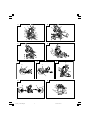 2
2
-
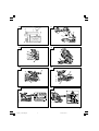 3
3
-
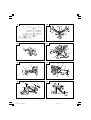 4
4
-
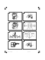 5
5
-
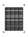 6
6
-
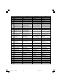 7
7
-
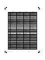 8
8
-
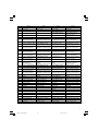 9
9
-
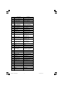 10
10
-
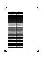 11
11
-
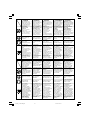 12
12
-
 13
13
-
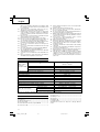 14
14
-
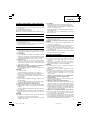 15
15
-
 16
16
-
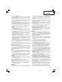 17
17
-
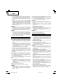 18
18
-
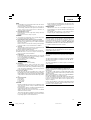 19
19
-
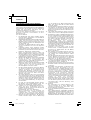 20
20
-
 21
21
-
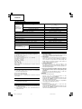 22
22
-
 23
23
-
 24
24
-
 25
25
-
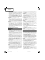 26
26
-
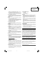 27
27
-
 28
28
-
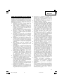 29
29
-
 30
30
-
 31
31
-
 32
32
-
 33
33
-
 34
34
-
 35
35
-
 36
36
-
 37
37
-
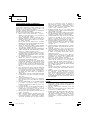 38
38
-
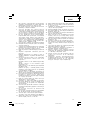 39
39
-
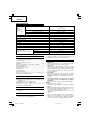 40
40
-
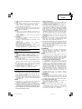 41
41
-
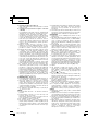 42
42
-
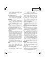 43
43
-
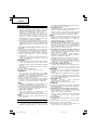 44
44
-
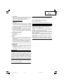 45
45
-
 46
46
-
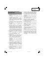 47
47
-
 48
48
-
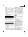 49
49
-
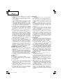 50
50
-
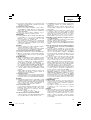 51
51
-
 52
52
-
 53
53
-
 54
54
-
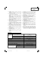 55
55
-
 56
56
-
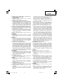 57
57
-
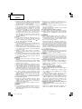 58
58
-
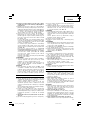 59
59
-
 60
60
-
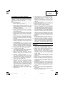 61
61
-
 62
62
-
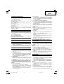 63
63
-
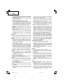 64
64
-
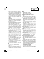 65
65
-
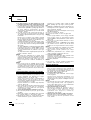 66
66
-
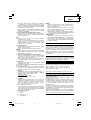 67
67
-
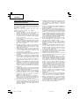 68
68
-
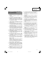 69
69
-
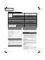 70
70
-
 71
71
-
 72
72
-
 73
73
-
 74
74
-
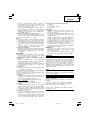 75
75
-
 76
76
-
 77
77
-
 78
78
-
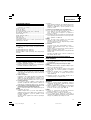 79
79
-
 80
80
-
 81
81
-
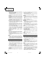 82
82
-
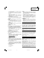 83
83
-
 84
84
-
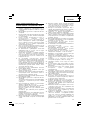 85
85
-
 86
86
-
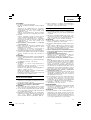 87
87
-
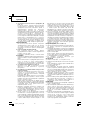 88
88
-
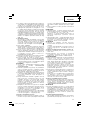 89
89
-
 90
90
-
 91
91
-
 92
92
-
 93
93
-
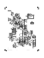 94
94
-
 95
95
-
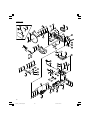 96
96
-
 97
97
-
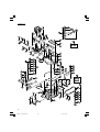 98
98
-
 99
99
-
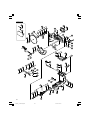 100
100
-
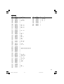 101
101
-
 102
102
-
 103
103
-
 104
104
-
 105
105
-
 106
106
-
 107
107
-
 108
108


Hikoki C 10FCE2 Manual de utilizare
- Categorie
- Ferăstraie mitre
- Tip
- Manual de utilizare
în alte limbi
- Türkçe: Hikoki C 10FCE2 Kullanım kılavuzu
- slovenčina: Hikoki C 10FCE2 Používateľská príručka
- polski: Hikoki C 10FCE2 Instrukcja obsługi
Lucrări conexe
-
Hikoki C8FSHE Slide Compound Miter Saw Instrucțiuni de utilizare
-
-
-
Hikoki C7ST Manual de utilizare
-
-
-
Hikoki WH18DSL Manual de utilizare
Alte documente
-
Ryobi RTMS1800 Original Instructions Manual
-
Hitachi C 8FSE Handling Instructions Manual
-
Makita MLS100 Manual de utilizare
-
Hitachi CR 13V2 Handling Instructions Manual
-
Makita LS1440 Manual de utilizare
-
Makita LS1018 Manual de utilizare
-
Makita LS1016L Manual de utilizare
-
Ryobi EJ700L Manualul proprietarului
-
-
Makita LB1200F Manual de utilizare